Method for producing crystallographically-oriented ceramic

a technology of crystallographic orientation and crystallographic orientation, which is applied in the direction of crystal growth process, basic electric elements, electrical apparatus, etc., can solve the problems of cumbersome processing and enhance crystallographic orientation, and achieve the effect of simple processing and enhanced crystallographic orientation

Inactive Publication Date: 2008-12-04
NGK INSULATORS LTD
View PDF10 Cites 4 Cited by
  • Summary
  • Abstract
  • Description
  • Claims
  • Application Information

AI Technical Summary

Benefits of technology

[0009]In the method for producing the crystallographically-oriented ceramic, a first shaped layer with a thickness of 10 μm or less containing a first inorganic material in which grain growth occurs at a predetermined first temperature or higher and a second shaped layer containing a second inorganic material in which grain growth occurs at a second temperature higher than the first temperature are formed, a laminated body is formed by laminating one or more each of the first shaped layer and the second shaped layer, and then the laminated body is fired at a temperature equal to or higher than the first temperature and lower than the second temperature to cause grain growth in the first inorganic material. In this stage, since the first shaped layer has a thickness of 10 μm or less, grain growth in the thickness direction of the layer is limited in the first inorganic material, and grain growth is more promoted in a direction along the contact surface with the second shaped layer. Subsequently, the laminated body is fired at a temperature equal to or higher than the second temperature to cause grain growth in the second inorganic material. In this stage, in the second inorganic material, grain growth proceeds along the direction of the grains of the first inorganic material which have grown along the contact surface. In such a manner, grain growth occurs in a certain direction as a whole. Consequently, it is possible to enhance crystallographic orientation by simple processing compared with a case where a first inorganic material in which grain growth has been caused by firing is crushed, the crushed first inorganic material is mixed and shaped with a second inorganic material, and the resulting shaped body is fired again.

Problems solved by technology

Thus, cumbersome processing is required to enhance the crystallographic orientation.

Method used


Image

  • Method for producing crystallographically-oriented ceramic
  • Method for producing crystallographically-oriented ceramic
  • Method for producing crystallographically-oriented ceramic

Examples


example 1

(Preparation Step of Preparing Inorganic Materials)

[0037]Powders (Li2CO3, Na2CO3, K2CO3, Nb2O5, and Ta2O5) were weighed so that a first inorganic material was composed of Li0.03(Na0.475K0.475)1.03NbO3.015 (an oxide represented by general formula ABO3 which is A-site rich) and a second inorganic material was composed of Li0.03(Na0.475K0.475)0.98Nb0.7Ta0.3O2.999 (A-site poor). With respect to each of the first and second inorganic materials, the weighed powders, zirconia balls, and ethanol as a dispersion medium were placed in a plastic pot, and wet mixing and pulverization were performed using a ball mill for 16 hours. The resulting slurry was dried using an evaporator and a dryer, and then calcination was performed at 850° C. for 5 hours. The calcined powder, zirconia balls, and ethanol as a dispersion medium were subjected to wet pulverization using a ball mill for 5 hours, followed by drying using an evaporator and a dryer. Thereby, inorganic material powders composed of Li0.03(Na...

example 2

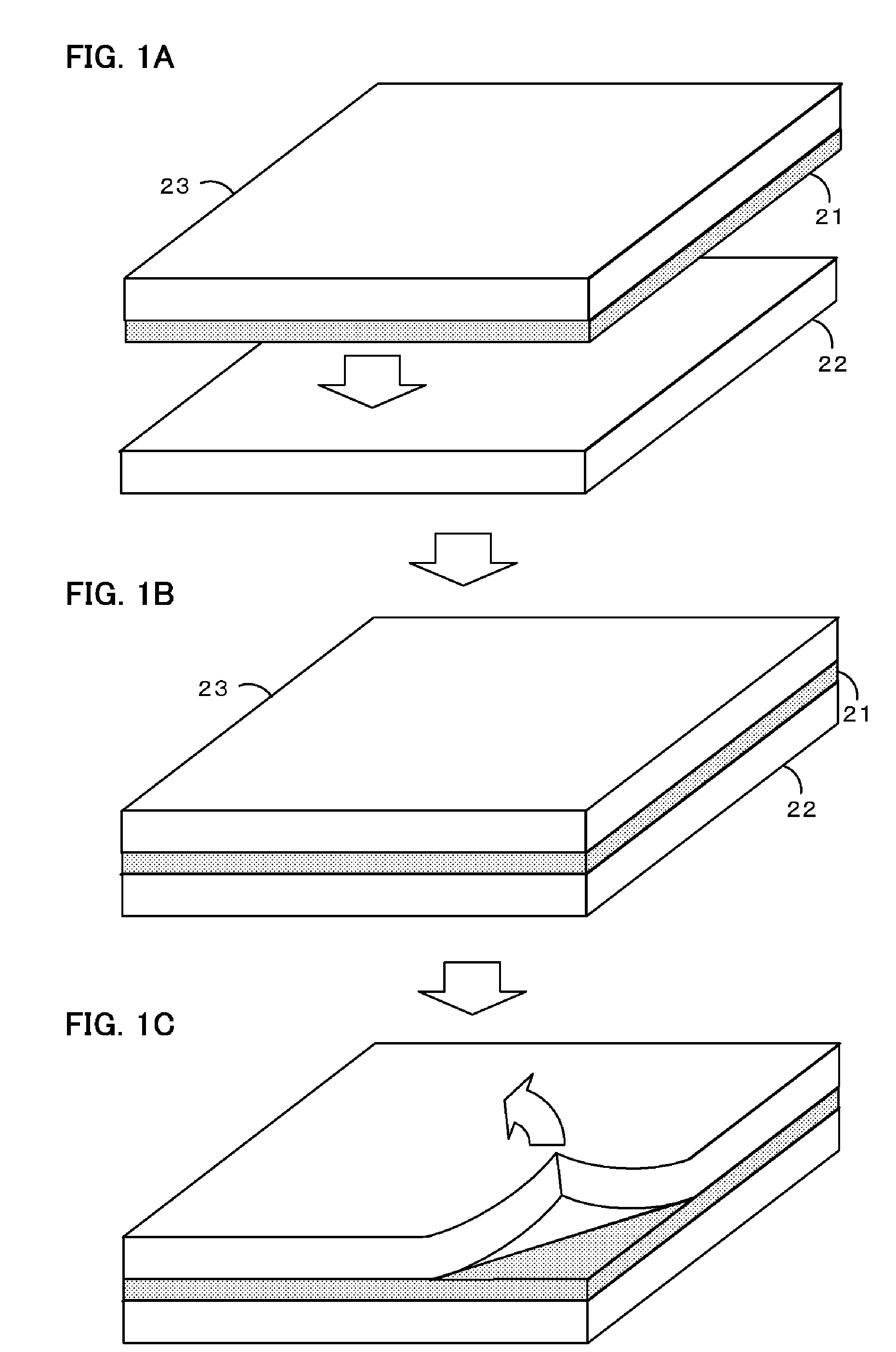
[0041]A crystallographically-oriented ceramic 40 was produced as in Example 1 except that, in the shaping step, through-holes 24 of 50 μm were formed by punching in the first sheets 21, and in the laminating step, lamination was performed such that the through-holes 24 of the two adjacent first sheets 21 were not aligned (refer to FIGS. 4A and 4B). After a laminating pressure was applied to the laminated body, a cross-section was checked, and it was found that the through-holes 24 were filled with the second inorganic material. In Example 2, it was evident that delamination did not easily occur during firing.

example 3

[0042]In the preparation step, a ZnO—B2O3—SiO2-based glass powder (ASF1891 manufactured by Asahi Glass (AGG)) (1% by weight) was added to a synthesized powder for a first inorganic material having the composition 0.2Pb(Mg0.33Nb0.67)O3-0.35PbTiO3-0.45PbZrO3 to which 1% by weight of NiO was added. The weighed mixture, zirconia balls, and ion-exchanged water as a dispersion medium were placed in a plastic pot, and wet mixing was performed using a ball mill for 16 hours. The resulting slurry was dried using a dryer, and then calcination was performed at 800° C. for 2 hours. The calcined powder, zirconia balls, and ion-exchanged water as a dispersion medium were subjected to wet pulverization using a ball mill, followed by drying using a dryer. Thereby, the first inorganic material was obtained. A second inorganic material was prepared as in the first inorganic material without using the ZnO—B2O3—SiO2-based glass powder. The grain growth temperature of the first inorganic material was 95...


PUM

PropertyMeasurementUnit
thicknessaaaaaaaaaa
aspect ratioaaaaaaaaaa
melting pointaaaaaaaaaa

Abstract

A method for producing a crystallographically-oriented ceramic includes the steps of forming a first sheet with a thickness of 10 μm or less containing a first inorganic material in which grain growth occurs at a first temperature or higher and a second sheet containing a second inorganic material in which grain growth occurs at a second temperature higher than the first temperature, laminating one or more each of the first and second sheets to form a laminated body, firing the laminated body at a temperature equal to or higher than the first temperature and lower than the second temperature to cause grain growth in the first inorganic material, and then firing the laminated body at a temperature equal to or higher than the second temperature to cause grain growth in the second inorganic material in the direction of a crystal plane of the first inorganic material.

Description

BACKGROUND OF THE INVENTION[0001]1. Field of the Invention[0002]The present invention relates to methods for producing crystallographically-oriented ceramics.[0003]2. Description of the Related Art[0004]To date, as the method for producing a crystallographically-oriented ceramic, a method has been proposed which includes a mixing step of mixing a host material A having shape anisotropy and a guest material B having crystal coherency with at least one crystal plane of the host material A and low crystal anisotropy, an orienting step of orienting a crystal plane of the host material A, and a firing step of heating the mixture to orient a crystal plane of the guest material B, and in which it is possible to obtain a ceramic with enhanced orientation even if the guest material B having low crystal anisotropy is used (for example, refer to Japanese Unexamined Patent Application Publication No. 10-330184).SUMMARY OF THE INVENTION[0005]However, in the method described in Japanese Unexamine...

Claims


Application Information

Patent Timeline
Patent Type & Authority Applications(United States)
IPC IPC(8): C03B29/00H01L41/39H01L41/43
CPCB32B18/00C04B35/493C04B35/495C04B35/64C04B2235/3201C04B2235/3203C04B2235/3206C04B2235/3251C04B2235/3279C04B2235/3284C04B2235/365C04B2235/5445C04B2235/6025C04B2235/656C04B2235/6562C04B2235/661C04B2235/768C04B2235/787C04B2235/79C04B2235/9623C04B2237/345C04B2237/346C04B2237/582C04B2237/62C04B2237/68C04B2237/704H01L41/43H01L41/1873Y10S117/902H10N30/8542H10N30/097
Inventor YOKOYAMA, SHOHEIKOBAYASHI, NOBUYUKINANATAKI, TSUTOMU
Owner NGK INSULATORS LTD
Why Eureka
Try Eureka