[0014]It is therefore one object of this invention to provide a fluid filled type vibration damping device, which is able to contrive to make component part commonization even if the specification of the valve and so on are different, and is able to do good part management.
[0030]On the other hand, the control-signals-generating circuit can be applied the same operation
processing program in either fluid filled type vibration damping device mounted on the different vehicle types or specification changed fluid filled type vibration damping device mounted on the same vehicle types. That is, the same control-signals-generating circuit can be applied in
spite of “the main body of the fluid filled type vibration damping device which include the valve and the coil” and “the power
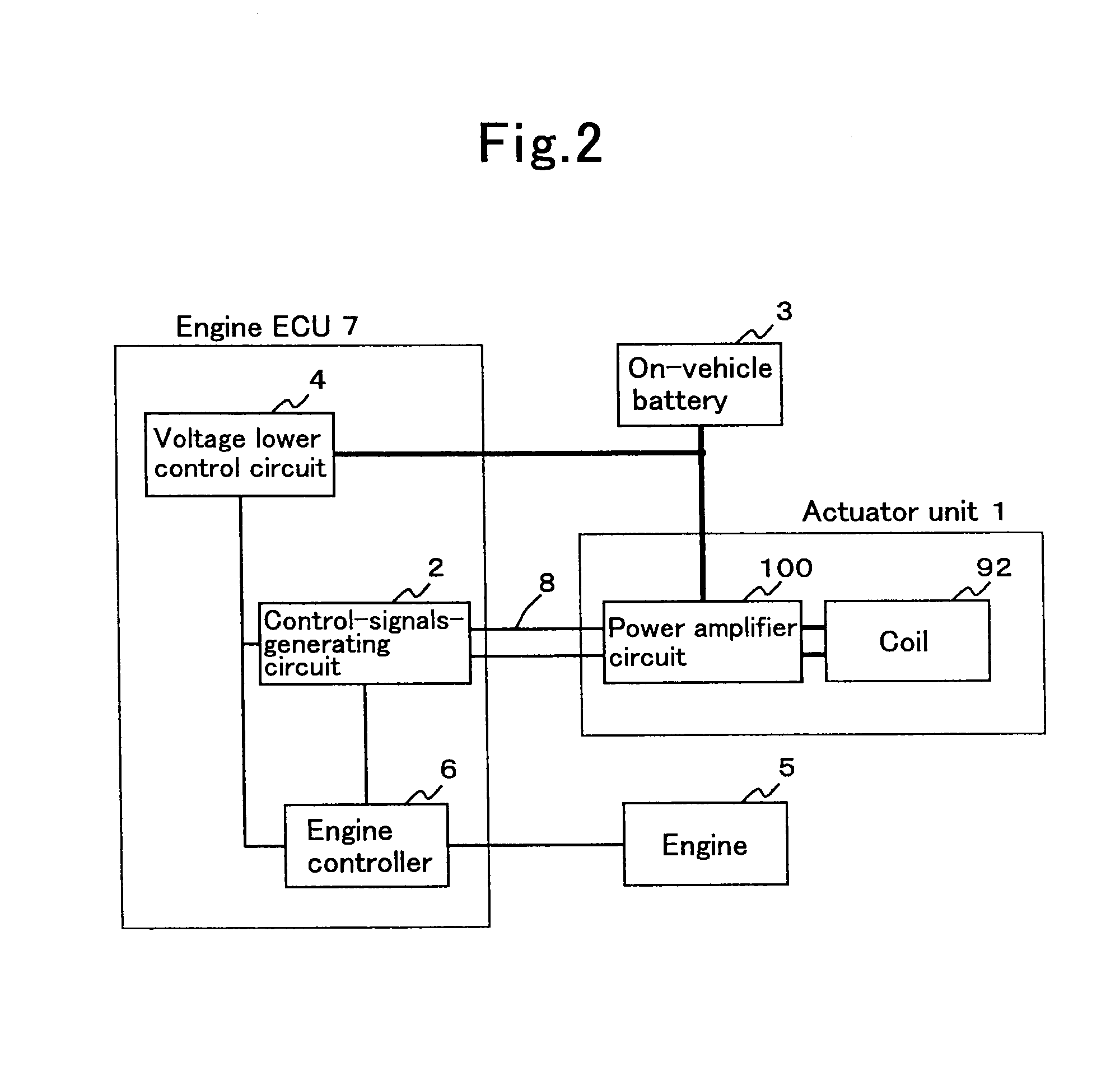
amplifier circuit” are different. And because of the control-signals-generating circuit is formed separately from the power amplifier circuit, irrespective of “the main body of the fluid filled type vibration damping device which include the valve and the coil” and “the power amplifier circuit”, the control-signals-generating circuit is able to be commonized. That is, part commonization of the control-signals-generating circuit in the fluid filled type vibration damping device mounted on the different vehicle types is able to be contrived. Therefore, it is able to make a low cost. Furthermore, in
spite of the case that the device specification of the fluid filled type vibration damping device mounted on the same vehicle types is changed, the control-signals-generating circuit does not need to be changed. Consequently, the specification change is able to be corresponded easily.
[0031]Furthermore, according to the present invention, “the main body of the fluid filled type vibration damping device which include the valve and the coil” and “the power amplifier circuit” which have a relation one to one, are attached integrally and constituted the
actuator unit. Because of unifying the both which have a relation one to one, the portion needed to be changed according to the specification can be grasped one part approximately. That is, the unique part according to one request specification is only one part of this unit. Therefore, because the main body of the fluid filled type vibration damping device and the power amplifier circuit are unified, the
cut of parts numbers of unique parts can be contrived. Therefore, because that is connected with the
cut of parts numbers of the whole fluid filled type vibration damping device, the management of parts comes to simply and to make a low cost is able to be contrived.
[0033]Here, to move the valve for switching the valve state, large
electromagnetic power is needed. But only to hold not to move the valve after switching, small
electromagnetic power is sufficient. Therefore, by supplying the electric-current to the coil for generating the necessary and sufficient
electromagnetic power to hold when the valve is held, it comes to be possible to curtail
electric power consumption of the coil when the valve is held. As a result, the calorific value of the coil is able to be restrained. Therefore, by
miniaturization of the coil and simplification of the coil
radiation structure, the
miniaturization of the main body of the fluid filled type vibration damping device is able to be contrived. Furthermore, by restraining of the calorific value of the coil, the temperature rise of the non-compressible fluid sealed in the fluid chamber is able to be restrained. Incidentally, if the temperature of the non-compressible fluid rise, the temperature of the main rubber elastic body constructing the fluid chamber sealing the non-compressible fluid rise and then there might arise a fear that the spring characteristics of the main rubber elastic body is affected. As a result, there might arise a fear that adequate vibration damping effect is not attained. However, according to the present invention, because the temperature rise of the fluid can be restrained, vibration damping effect is able to be attained adequately.
[0034]Furthermore, when the power amplifier circuit comprised the fluid filled type vibration damping device according to the present invention is equipped with a switching element and amplify the
state switching control signals by being switched the switching element, to adopt above construction is effective. Thus, to switch the switching element is very easy and is able to control with high accuracy.
[0039]Furthermore, in the case that idling vibration, which is the
high frequency band, occurs, the flowing force of the non-compressible fluid get smaller compared with in the case that shake vibration, which is the
low frequency band, occurs. That is, in the case that the flowing force of the non-compressible fluid becomes small, by the electromagnetic force affecting by the
electrical connection to the coil, the valve is made to move and hold. Therefore, the electromagnetic force to make to move the valve and the electromagnetic force to hold the valve with the state, that the valve was moved, are able to be made small. Therefore, the electric-current to supply to the coil is able to be curtailed. As a result, the
electric power consumption of the coil is able to be curtailed. That makes to restrain the calorific value of the coil. As a result, with the
miniaturization of the main body of the fluid filled type vibration damping device is able to be contrived, the adequate vibration damping effect is able to be attained.

