Filter-based lock-in circuits for PLL and fast system startup
Inactive Publication Date: 2008-12-04
SMART SEMICON LLC +3
View PDF4 Cites 16 Cited by
Summary
Abstract
Description
Claims
Application Information
AI Technical Summary
This helps you quickly interpret patents by identifying the three key elements:
Problems solved by technology
Method used
Benefits of technology
[0012]Consequently, all filter-based lock-in circuits solve serious harmonic locking problems and provide a fast lock-in time so that any system including PLL should not have long wait time. In a
Problems solved by technology
However, the conventional phase-locked loops 110 and 120 have suffered from slow locking, which has increased system startup time.
However, PLL synthesizers for wireless applications must provide fast lock-in time.
However, if a PLL has a slow lock-in time performance, it will prohibit the PLL behavior from being incorporated into the complete and realistic system simulation.
The PLL behavior without lock-in time degrades simulation accuracy and adds serious bottleneck to the complete and realistic system simulation.
Moreover, the speed of system bootup time has also been degrad
Method used
Image
Click on the blue label to locate the original text in one second.
Reading with bidirectional positioning of images and text.
Examples
Embodiment Construction
[0026]In the following detailed description of the present invention, the filter-based lock-in circuits for phase-locked loop and fast system start-up time, numerous specific details are set forth in order to provide a thorough understanding of the present invention. However, it will be obvious to one skilled in the art that the present invention may be practiced without these specific details. In other instances, well known methods, procedures, CMOS digital gates, components, and metal-oxide-semiconductor field-effect transistor (MOSFET) device physics have not been described in detail so as not unnecessarily obscure aspects of the present invention.
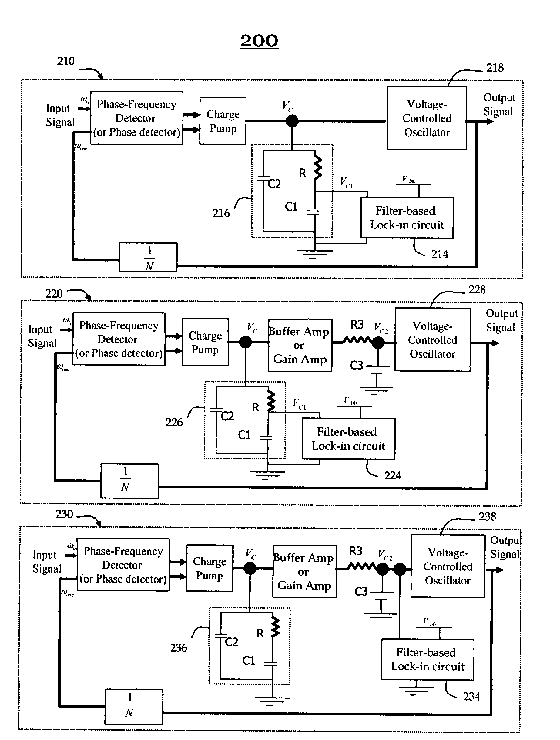
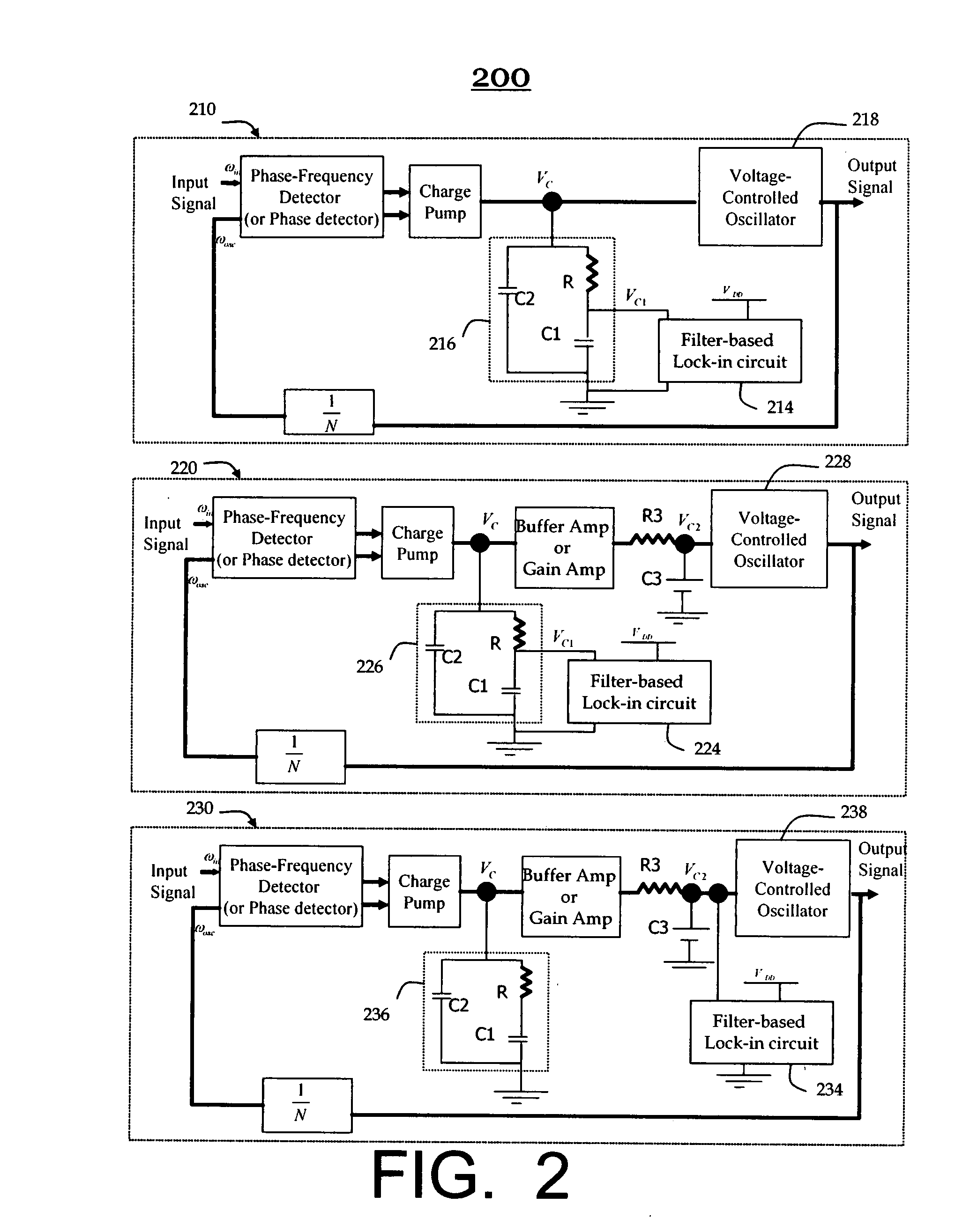
[0027]FIG. 2 illustrates three exemplary embodiments of a phase-locked loop including a block diagram of a filter-based lock-in circuit in accordance with the present invention. A first block diagram of a filter-based lock-in circuit 214 has a single bidirectional node, which is connected to a junction between a resistor R and a capacit...
PUM
Abstract
All embodiments of the present invention basically include an upper transistor and a lower transistor connected in series between a power supply and ground. The upper transistor and the lower transistor have a shared source (or drain) terminal which becomes a single bidirectional node. They further comprise a sensing gate and a logic gate. The sensing inverter has a function of sensing a voltage at the single bidirectional node and comparing it with an input transition voltage since an input terminal of the sensing inverter is connected to the single bidirectional node. An initial voltage at the single bidirectional node of the filter-based lock-in circuit is almost the same as the input transition voltage of the sensing inverter, where the input transition voltage is an input voltage which causes an output voltage to be VDD/2. Consequently, all embodiments of the present invention provide a fast lock-in time performance and achieve a drastic improvement in system startup time, system latency time, system simulation time, system test time, cost, and time to market
Description
FIELD OF THE INVENTION[0001]The present invention relates to the field of filter-based lock-in circuit for fast system startup more particularly to phase-locked loop and very fast system startup using filter-based lock-in circuitBACKGROUND ART[0002]Phase-looked loop is a vitally important device. Phase-looked loop is analog and mixed signal building block used always in subsystem, system-on-chip, system IC, memory, telecommunication, communication, navigation system, computer, computer peripherals, automotive, networks, digital systems, consumer electronics, industrial, instrumentation, and any other fields that require frequency synthesizing, clock recovery, synchronization, clock generation, and / or the system's clock distribution. Phase-looked loop is a very versatile building block suitable for a variety of frequency synthesis, clock recovery, clock generation, and synchronization applications.[0003]Prior Art FIG. 1 shows two types of conventional phase-locked loops, which are a ...
Claims
Application Information
Patent Timeline
Application Date:The date an application was filed.
Publication Date:The date a patent or application was officially published.
First Publication Date:The earliest publication date of a patent with the same application number.
Issue Date:Publication date of the patent grant document.
PCT Entry Date:The Entry date of PCT National Phase.
Estimated Expiry Date:The statutory expiry date of a patent right according to the Patent Law, and it is the longest term of protection that the patent right can achieve without the termination of the patent right due to other reasons(Term extension factor has been taken into account ).
Invalid Date:Actual expiry date is based on effective date or publication date of legal transaction data of invalid patent.