Phase-locked loop with incremental phase detectors and a converter for combining a logical operation with a digital to analog conversion

a phase detector and converter technology, applied in the direction of angle demodulation, automatic control of pulses, transmission, etc., can solve the problems of reducing the overall performance of the system, and reducing the over-all performance of the radio system, so as to reduce the risk of sub-harmonics, the effect of fast lock-in time and simple circui

Inactive Publication Date: 2008-09-16
R & C HLDG APS
View PDF11 Cites 0 Cited by
  • Summary
  • Abstract
  • Description
  • Claims
  • Application Information

AI Technical Summary

Benefits of technology

[0014]An object of the present invention is to provide an improved phase-locked loop, which may have a fast lock-in time, minimum risk for sub-harmonics in the output, and which can be implemented in a simple circuit.

Problems solved by technology

When using a conventional phase-locked loop some unwanted frequency components or spurious occur in the output signal.
The spurious are an unwanted effect as it most often reduces the overall performance of the system in which the phase-lock loop is operating.
For example, spurious on the carrier in a radio system is a disadvantage as it causes undesired channels to interfere with the desired channel and thereby reducing the over-all performance of the radio system.
But the price of reducing the bandwidth of the loop filter is a slower PLL, i.e. the lock-in time for the PLL is increased.
Some if not most prior art phase-locked loops, which are fully or partly implemented using digital components, also have a risk of producing sub-harmonic frequencies due to the way they are implemented.
They also increase the complexity of the PLL-circuit considerably and do not improve on the lock-in time for the PLL, because a loop filter with a narrow bandwidth is still needed.
However, the two aggregated signals from the two accumulators are asynchronous signals, thereby generating a problem for the subtraction process.

Method used


Image

  • Phase-locked loop with incremental phase detectors and a converter for combining a logical operation with a digital to analog conversion
  • Phase-locked loop with incremental phase detectors and a converter for combining a logical operation with a digital to analog conversion
  • Phase-locked loop with incremental phase detectors and a converter for combining a logical operation with a digital to analog conversion

Examples


first embodiment

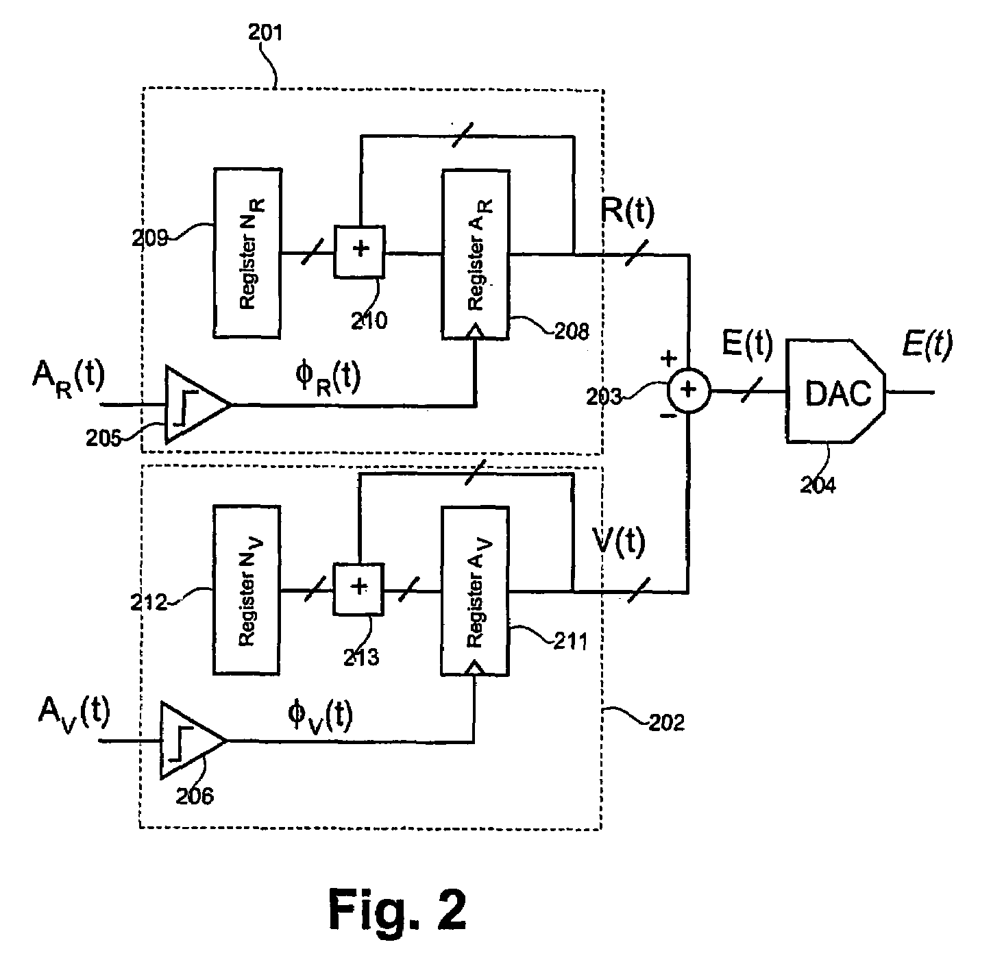
[0194]FIG. 2 illustrates a phase comparator or frequency comparator according to the invention. The phase comparator includes a first accumulator 201, a second accumulator 202 and subtracting means 203. The first accumulator 201 and the second accumulator 202 both include an input terminal and an output terminal. The first and the second accumulator 201, 202 are operatively connected to a first and a second input terminal of the subtracting means203. The first and the second accumulator 201, 202 are both adapted for receiving an input signal via the input terminal and generating an output signal, which is supplied to the subtracting means. Responsive to the input signal received via the input terminal of the accumulator 201, the first accumulator 201 is adapted for accumulating a first value in a register or memory thereof. Likewise, responsive to the input signal received via the input terminal of the accumulator 202, the second accumulator 202 is adapted for accumulating a second ...

second embodiment

[0199]The above-mentioned embodiment is advantageous due to the simplicity, which is obtained due to the calculation of the phase error as a digital subtraction. The price, on the other hand, is that the digital subtraction may generate spikes and hazards in the resulting phase error signal. In the following a phase comparator according to the invention is described. This embodiment is an example of a phase comparator which is both simple and hereby easy to implement, and in which spikes and hazards do not occur in the resulting output signal.

[0200]FIG. 3 illustrates a second embodiment of a phase comparator according to the invention. In this embodiment, the first and the second accumulator 201, 202 is implemented as described in relation to FIG. 2. Therefore the first and the second accumulator 201, 202 and the function thereof will not be described further below.

[0201]In contrast to the embodiment shown in FIG. 2, the output of the first and the second accumulators 201, 202 in th...

third embodiment

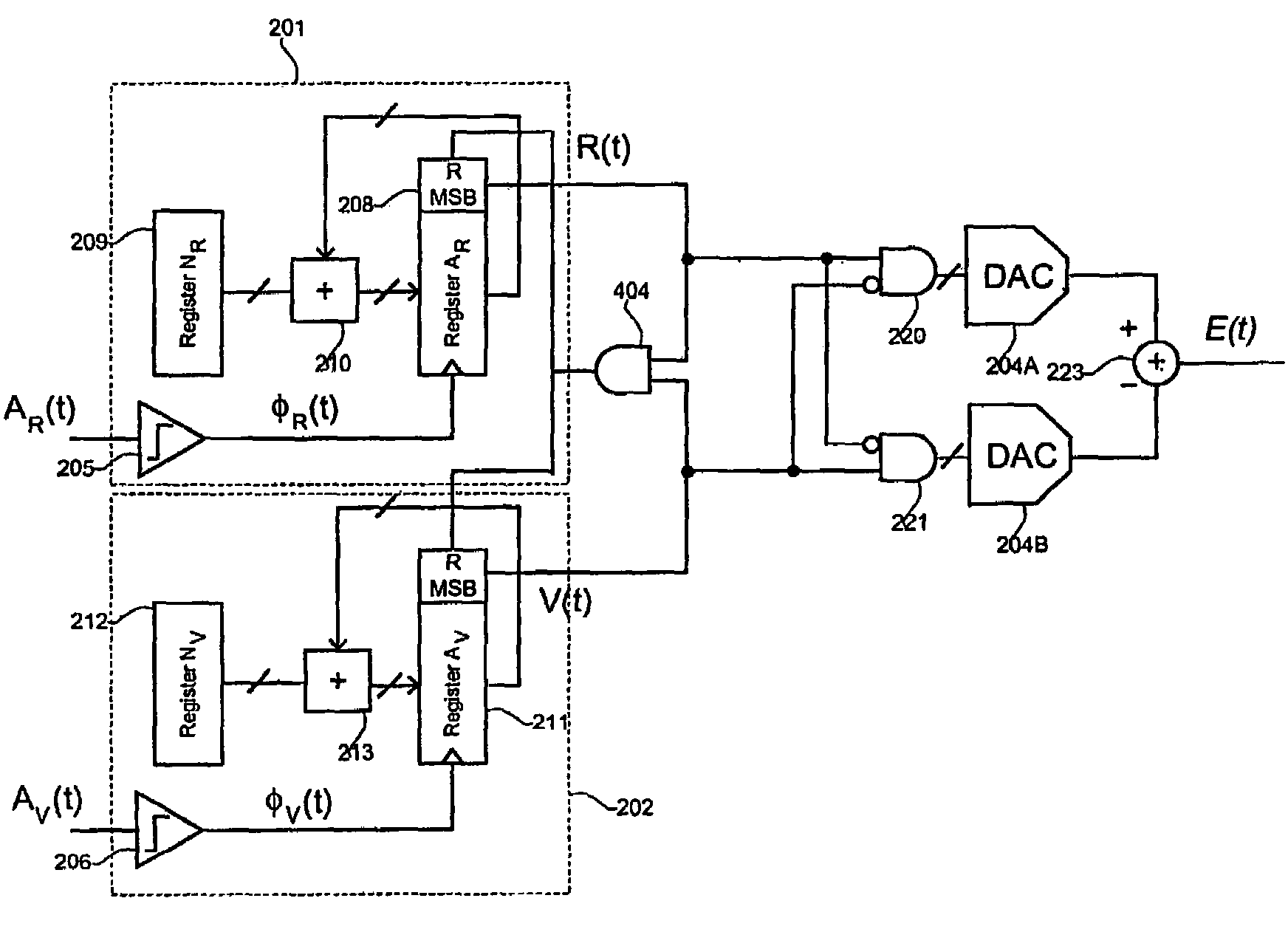
[0206]FIG. 4 illustrates a phase comparator according to the invention. The shown embodiment includes a synchronous reset of the most significant bit (MSB) of the first register 208 and the third register 211, i.e. the registers adapted for including accumulated values. It is, however, not the absolute value of the digital number in the registers, but the difference between the numbers. The synchronous reset may be implemented as illustrated in FIG. 4. In the shown embodiment the first register 208 and the third register 211 have the same length, i.e. the two registers include the same number of bits. When the phase comparator is in use the contents of the two registers are accumulated as a result of the above-mentioned trigger signal supplied thereto. As the difference between the contents of the two registers is calculated, it has to be insured that a possible overflow of the registers is taken care of. This is due to the fact that an uncontrolled overflow may otherwise lead to an...


PUM


Abstract

The invention relates to a phase-locked loop comprising a voltage controlled oscillator and having a frequency control input for controlling the frequency of the output signal. The phase-locked loop also has a phase comparator for deriving a control signal from a phase error detected in response to a received output signal and a reference signal. The control signal is coupled to the frequency control input of said voltage controlled oscillator. The phase comparator includes a first and a second predefined phase step value to a first accumulated phase value, and the phase comparator has means for determining the phase error. The phase comparator may further have circuit means for performing a first and a second AND operation on the outputs from the first and second accumulators and for obtaining analogue signals corresponding to the outputs of the AND operations. The invention also relates to a method for obtaining information on a phase error between two signals. The invention also relates to a phase comparator for use in a phase-locked loop. The invention further relates to a digital to analogue converter, which converter may combine a logic operation with a digital to analogue conversion.

Description

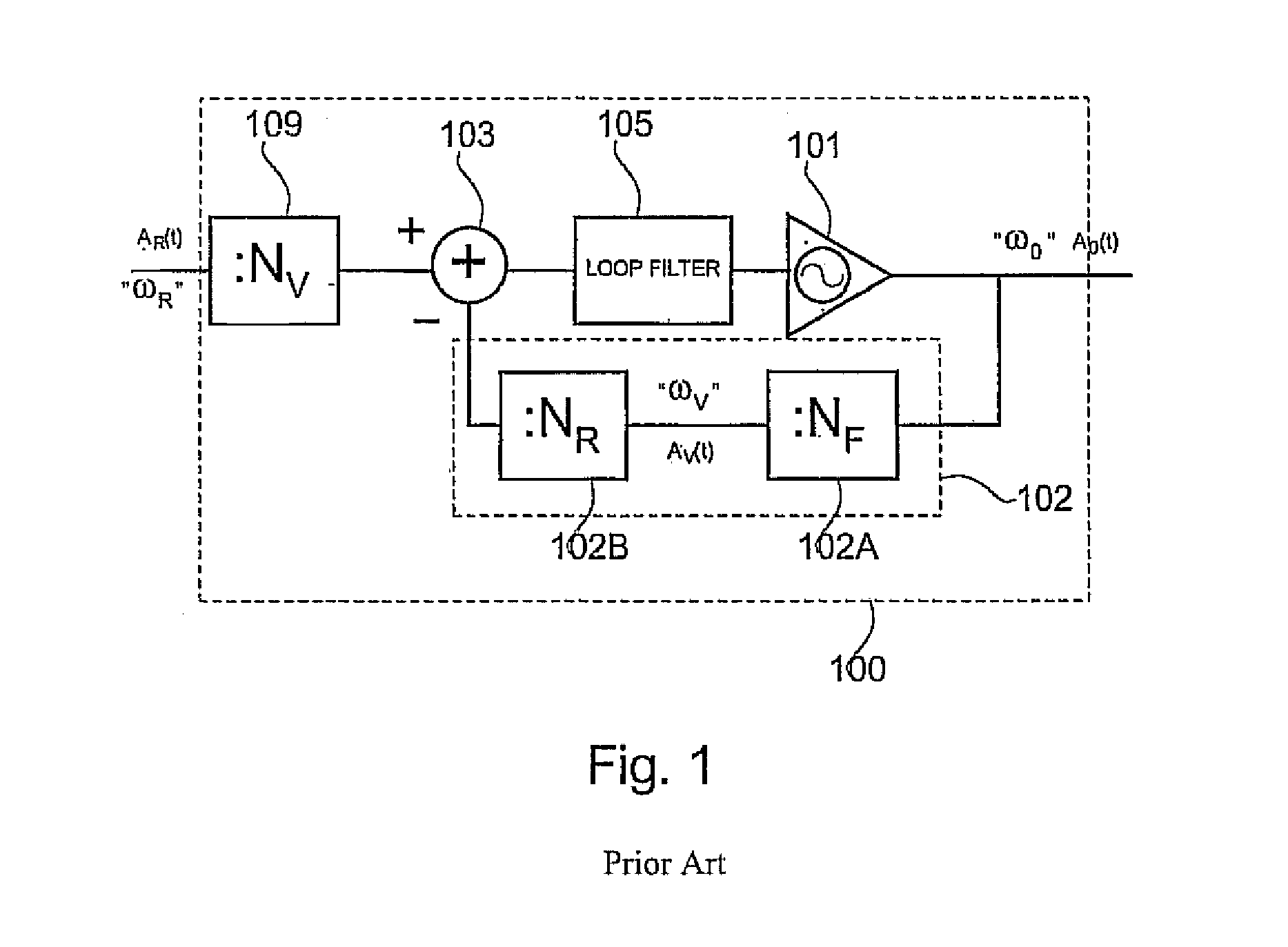
FIELD OF THE INVENTION[0001]The present invention relates to a phase-locked loop, and more particularly to a phase-locked loop having a phase comparator with a phase error being derived from the outputs of incremental phase detectors.[0002]The invention also relates to a method for determining a phase error in response to a first signal and a second signal and a phase comparator for carrying out the method.[0003]The present invention further relates to a digital to analogue converter, and more particularly to a converter for combining a logical operation with a digital to analogue conversion.BACKGROUND OF THE INVENTION[0004]Phase-locked loops are used in a variety of applications. In general, phase-locked loops include a phase comparator or phase detector to compare the phase of a frequency-divided output signal of the voltage controlled oscillator and a reference signal. The difference between these two signals is used to generate a control signal or error signal, which is fed back...

Claims


Application Information

Patent Timeline
Patent Type & Authority Patents(United States)
IPC IPC(8): H03L7/06H03L7/091H03L7/18
CPCH03L7/18H03L7/091H03L7/1806
Inventor RASMUSSEN, CARSTEN
Owner R & C HLDG APS
Why Eureka
Try Eureka