Apparatus and method for reducing the die area of a PWM controller

a controller and die area technology, applied in the field of apparatus and methods for reducing can solve the problems of higher cost, more complex circuits and die areas, and better function, so as to reduce the cost, reduce the die area of a pwm controller, and reduce the cost

Inactive Publication Date: 2008-12-04
RICHTEK TECH
View PDF1 Cites 52 Cited by
  • Summary
  • Abstract
  • Description
  • Claims
  • Application Information

AI Technical Summary

Benefits of technology

[0006]An object of the present invention is to provide an apparatus and method for reducing the die area of a PWM controller.
[0007]Another object of the present invention is to provide an apparatus and method for preventing a PWM controller from suffering interference between the protection circuit and frequency jittering circuit thereof.
[0008]According to the present invention, an apparatus and method for reducing the die area of a PWM controller include extracting a fault index signal from the PWM controller to signal a fault event, and triggering a protection function by a protection circuit according to a low frequency clock and the fault index signal.
[0009]Specifically, the present invention provides an approach to reduce cost and maintains functions of a PWM controller. Since the protection function is triggered by monitoring the low frequency clock and fault index signal, there will be no need of any fault detection circuits and complex clock diverting circuit. Furthermore, because the protection circuit can be completely separated from the frequency jittering circuit, both of them can operate independently from mutual interference. Thereupon, the circuit is simplified, and the die area and cost of the PWM controller are reduced.

Problems solved by technology

However, better function generally means more complex circuit and larger die area, and thereby higher cost.
The size of an EMI filter increases with the increasing of the EMI noise to be filtered out.
Frequency jittering is the trend in the latest AC / DC converter because it saves the cost in EMI filtering.
Typically, a T flip-flop costs the same area as a 5 pF capacitor, and a big counter consumes relatively large die area accordingly.
Analog frequency jittering circuit generates a low frequency envelop by charging a large capacitor with a small current and therefore, it also consumes a relatively large die area.
Though frequency jittering facilitates reducing the size of EMI filter, it disadvantageously bulks the size of a PWM controller.
These circuits significantly increase the die area and cost of a PWM controller.
However, a PWM controller may include some other functions which take long time for event verification, for example the detections of overload, light load, feedback open, optocoupler short or brownout.
It is very area consuming to generate a long time constant in an IC.
Consequently, reducing the die area of a PWM controller is limited.

Method used


Image

  • Apparatus and method for reducing the die area of a PWM controller
  • Apparatus and method for reducing the die area of a PWM controller
  • Apparatus and method for reducing the die area of a PWM controller

Examples


Embodiment Construction

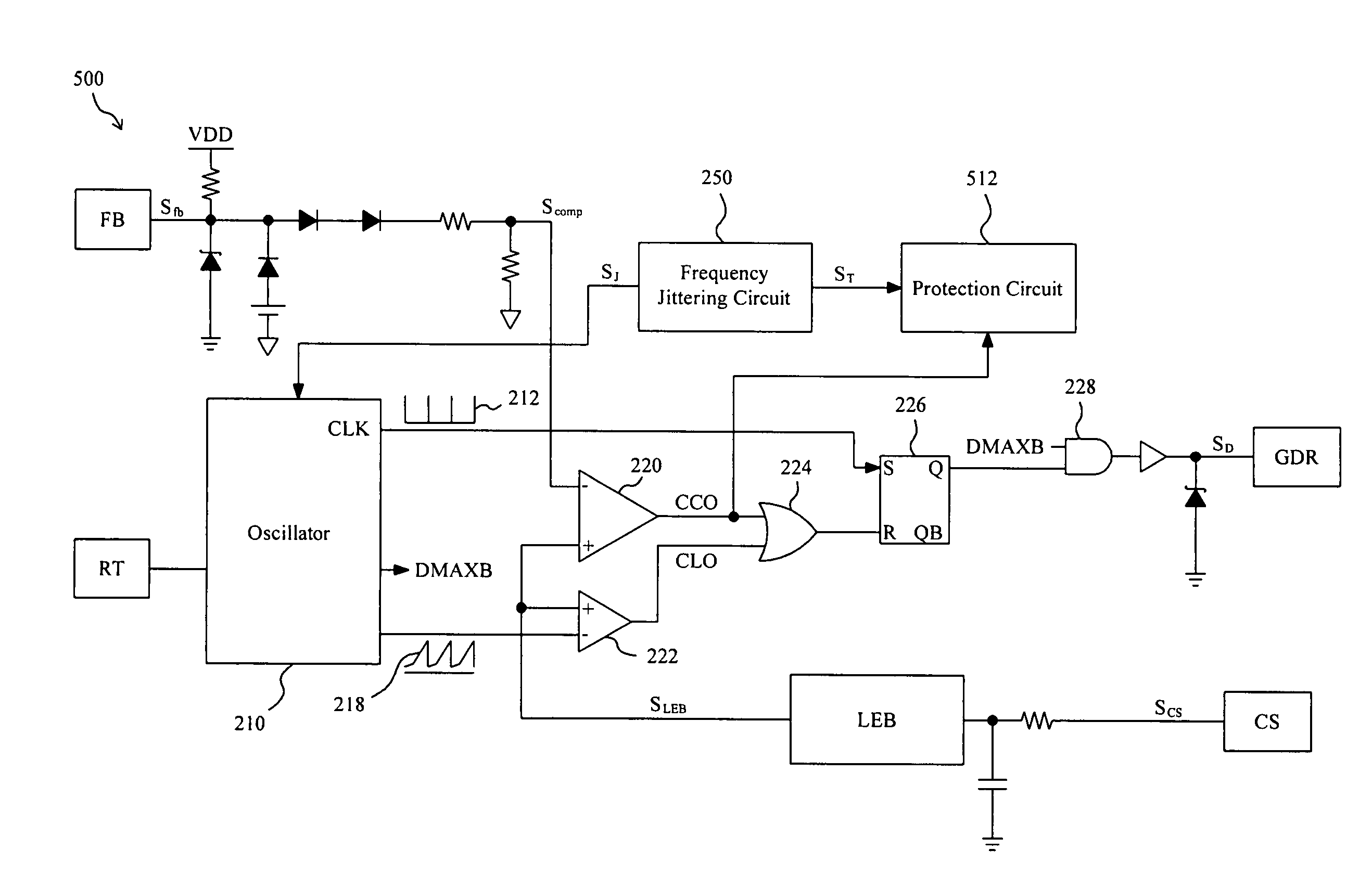
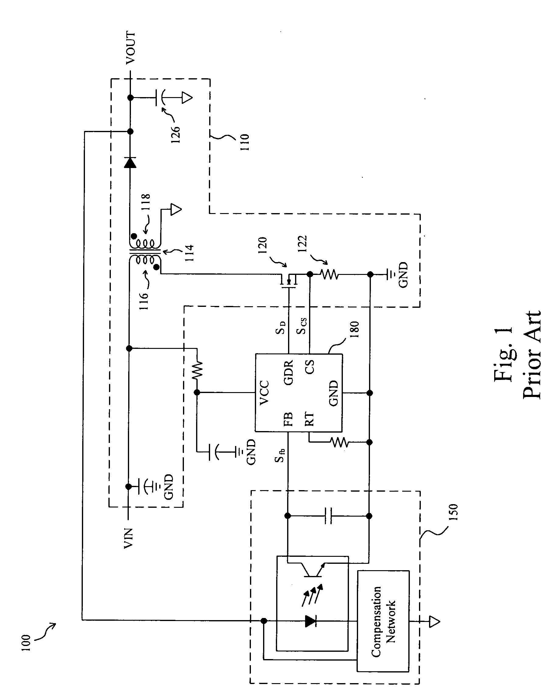
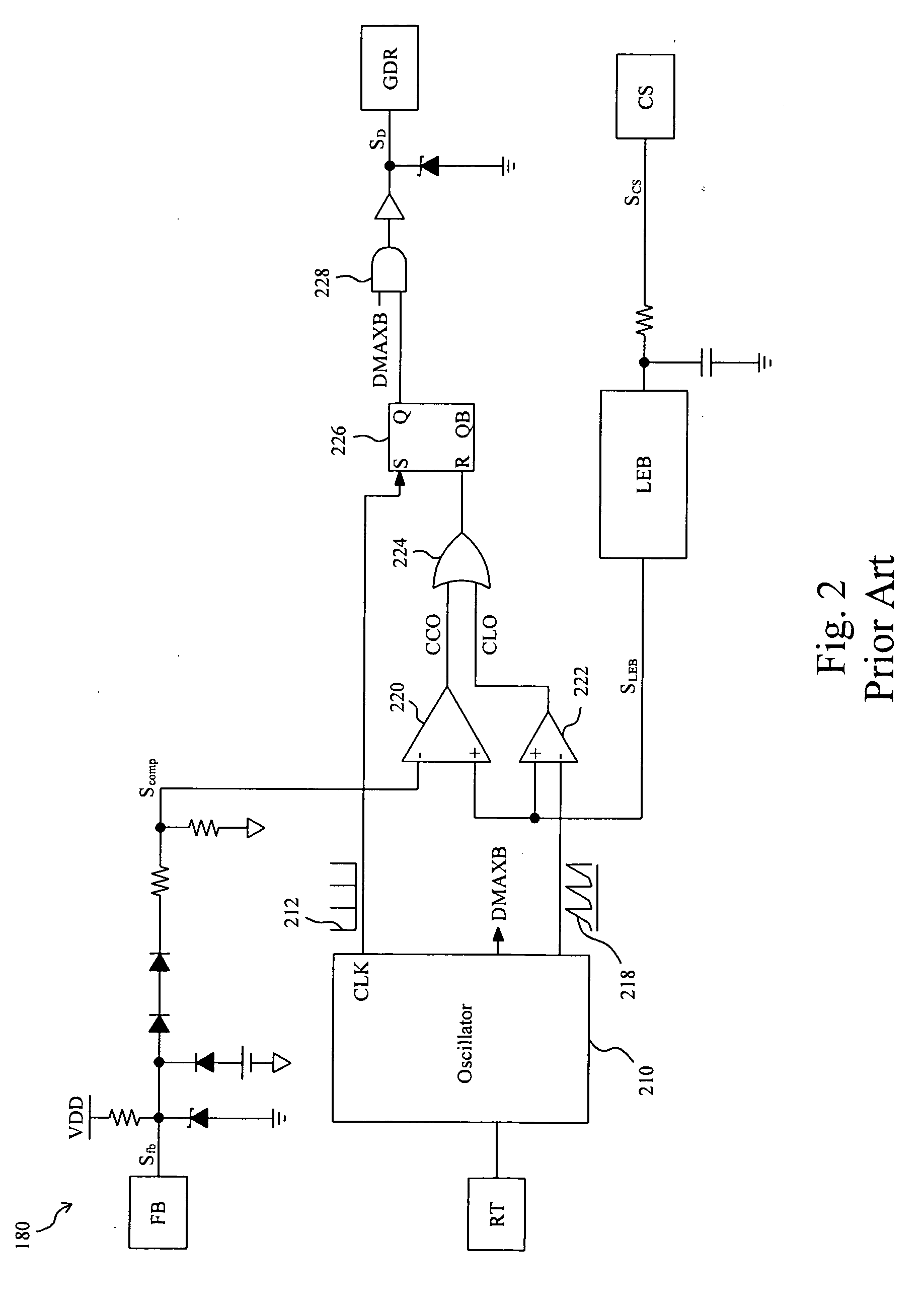
[0019]It can be learned from FIGS. 1 and 2 that the PWM controller 180 generates the maximum duty limit DMAXB and signals CCO and CLO according to the status of the flyback converter 100 for the control of the switch 120. Under normal operation of the flyback converter 100, the PWM controller 180 generates the PWM signal SD according to the current comparator output CCO to switch the switch 120; while fault occurs, the current comparator output CCO vanishes and the PWM controller 180 generates the PWM signal SD according to the current limiting output CLO or the maximum duty limit DMAXB instead to switch the switch 120. In other words, the current comparator output CCO can be selected as a fault index signal among all faults and as long as the current comparator output CCO appears, that means no fault occurring.

[0020]Accordingly, FIG. 5 provides a PWM controller 500 with the same configuration as that of FIG. 2 and, dissimilarly, having the current comparator output CCO as a fault i...


PUM


Abstract

An apparatus and method for reducing the die area of a PWM controller include a protection circuit triggered by a fault index signal for counting, and the counting time is provided for a delay time required by fault verification. Therefore, fault detection circuits can be eliminated and the purpose of reducing the die area can be achieved.

Description

FIELD OF THE INVENTION[0001]The present invention is related generally to a pulse width modulation (PWM) controller and, more particularly, to an apparatus and method for reducing the die area of a PWM controller.BACKGROUND OF THE INVENTION[0002]For standing out in the highly competitive market, better function and lower cost are two key factors for integrated circuit (IC) products. However, better function generally means more complex circuit and larger die area, and thereby higher cost. As shown in FIG. 1, a flyback converter 100 uses a PWM controller 180 to operate it in constant frequency current mode and processing the line voltage VIN into an isolated direct current (DC) output voltage VOUT. The PWM controller 180 provides a PWM signal SD for a power stage 110, and a feedback circuit 150 generates a feedback signal Sfb for the PWM controller 180 according to the output voltage VOUT in order to regulate the output voltage VOUT within an adjustable range. In the power stage 110,...

Claims


Application Information

Patent Timeline
Patent Type & Authority Applications(United States)
IPC IPC(8): H02H7/12
CPCH02M1/32H02M1/44
Inventor HUANG, PEI-LUNFAN, CHENG-HSUAN
Owner RICHTEK TECH
Why Eureka
Try Eureka