
Adaptive rectifier Architecture and method for switching regulators

a rectifier and adapter technology, applied in the direction of electric variable regulation, process and machine control, instruments, etc., can solve the problems of node sw increase, node sw loss, and negative impact on efficiency, so as to improve the accuracy of zero-crossing detection and boost the efficiency of the power supply

Active Publication Date: 2008-12-04
TEXAS INSTR INC
View PDF12 Cites 77 Cited by
  • Summary
  • Abstract
  • Description
  • Claims
  • Application Information

AI Technical Summary

Benefits of technology

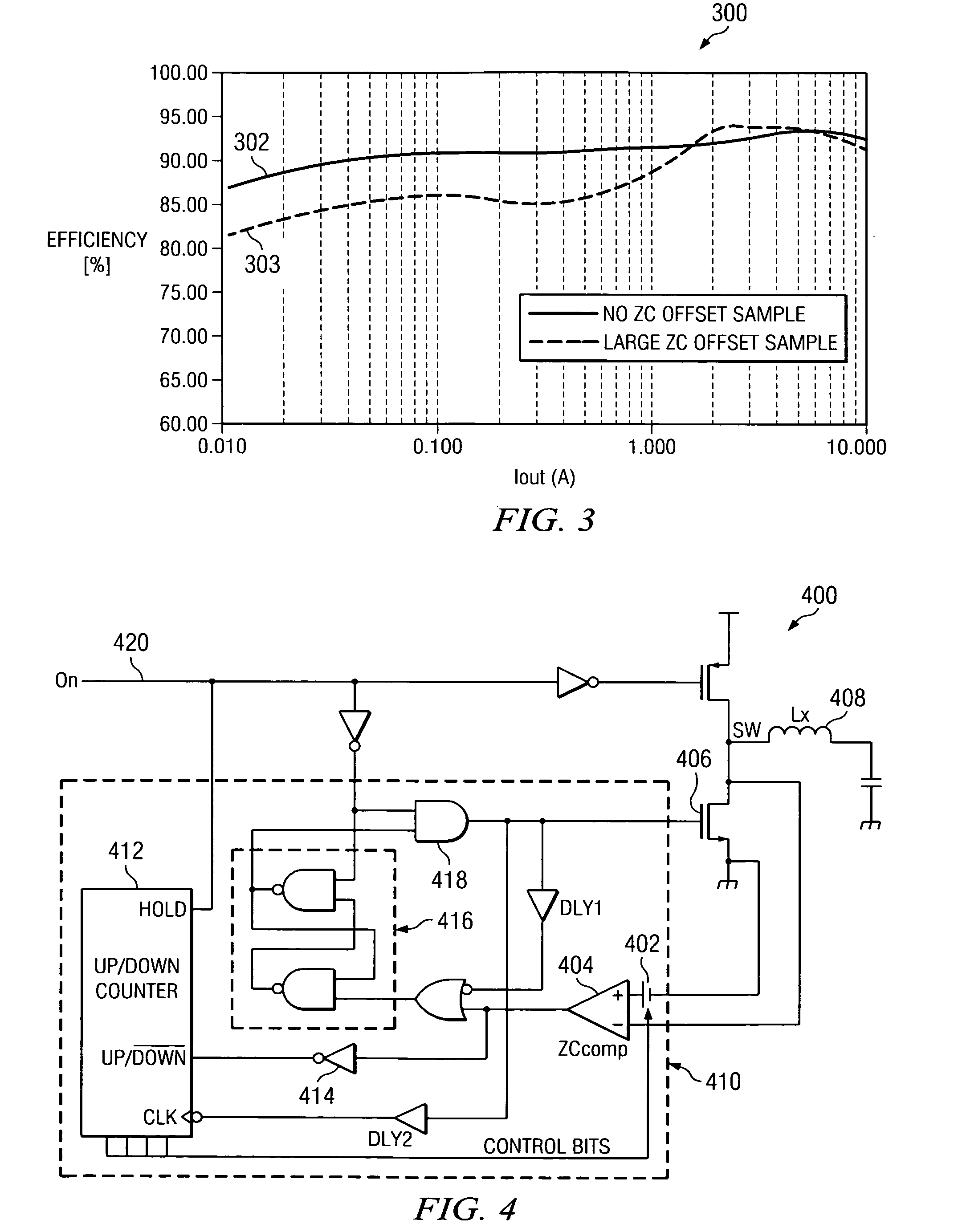
[0011]The disclosed system and method provide a dynamic adjustment to a comparator controlling switching in an inductor based power supply. The comparator operation is dynamically adjusted to improve the accuracy of a zero crossing detection for inductor current in a switching power supply operating in discontinuous or transition mode to boost the efficiency of the power supply in light load conditions.
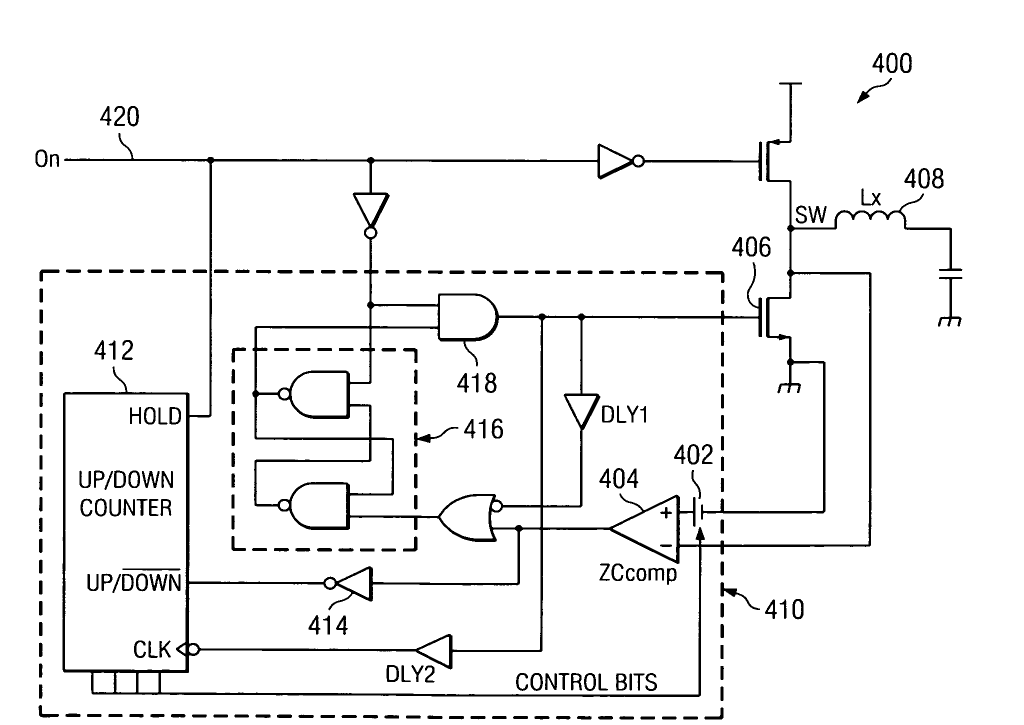
[0014]According to an exemplary embodiment, a rectifying MOSFET in a switching power supply is turned off and, after a suitable delay, a voltage offset generator is updated with information concerning the timing of the zero crossing. If the zero crossing is detected by the comparator later than when the MOSFET is turned off, the voltage offset generator reduces a compensation voltage offset applied to a comparator. In the next switching cycle, the comparator changes state earlier, so that the MOSFET is turned off earlier. If the comparator detects a zero crossing earlier than when the MOSFET is turned off, the voltage offset generator increases the compensation offset voltage applied to the comparator. In the next switching cycle, the comparator changes state later, so that the MOSFET is turned off later. After several switching cycles, the compensation offset voltage is adjusted for appropriate timing to turn off of the MOSFET in close proximity to the zero current crossing, thereby improving and maintaining the zero current crossing detection accuracy.

Problems solved by technology

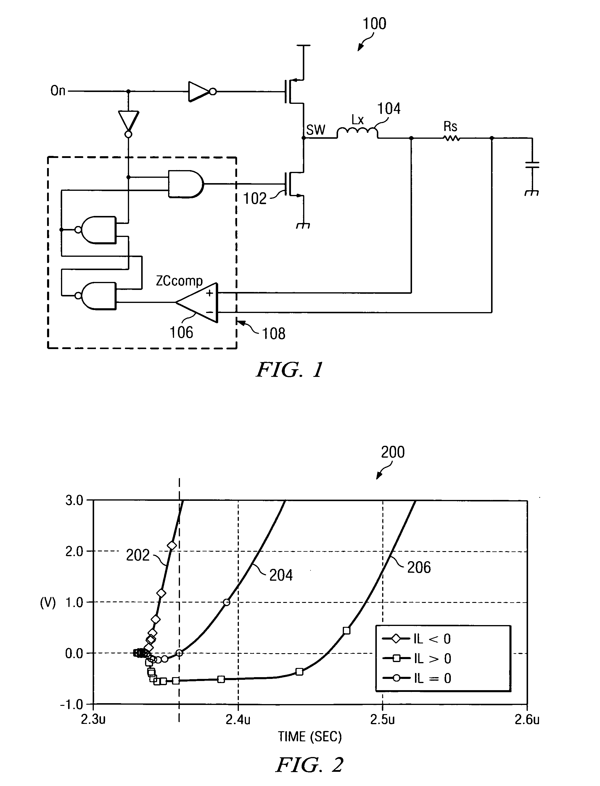
For example, if MOSFET 102 is turned off before the current in inductor 104 reaches zero, a body diode of MOSFET 102 conducts, leading to conduction losses that can negatively impact efficiency.
If MOSFET 102 is turned off after the current in inductor 104 has passed zero to become negative, the voltage at switching node SW increases sharply to the input voltage level and MOSFET 102 experiences switching losses that negatively impact efficiency.
Thus, the offset voltage and deviations in the value of the offset voltage can degrade circuit performance due to increased conduction and switching losses, as mentioned above.
The delay can cause inaccurate timing for turning off MOSFET 102.
It is difficult to set the compensation voltage accurately with respect to the value of sense resistor Rs to avoid negatively impacting light-load efficiency.
A static compensation voltage is unable to adequately compensate for the dynamic conditions present in power stage 100 under normal operating conditions.

Method used


Image

  • Adaptive rectifier Architecture and method for switching regulators
  • Adaptive rectifier Architecture and method for switching regulators
  • Adaptive rectifier Architecture and method for switching regulators

Examples


Embodiment Construction

[0026]This application is based on and claims benefits of provisional application number 60 / 940,736, filed May 30, 2007, the entire disclosure of which is hereby incorporated herein by reference.

[0027]The disclosed system and method provides an adaptive rectifier configuration that automatically compensates for a comparator offset voltage and a propagation delay in a switching control for a power supply operating in discontinuous or transition conduction mode.

[0028]Referring now to FIG. 2, a graph 200 illustrates plots of voltage at node SW in power stage 100 in FIG. 1. The voltage plots show voltage in relation to timing for synchronous rectifier turn-off events. Line 202 illustrates synchronous rectifier turn-off after inductor current has become negative. Line 204 illustrates synchronous rectifier turn-off when inductor current is approximately zero. Line 206 illustrates synchronous rectifier turn-off before inductor current has reached zero. In the case of line 202, the synchron...


PUM


Abstract

An adjustable compensation offset voltage is applied to a comparator to vary turn-off timing of a synchronous rectifier. A comparator output indicates when current through an inductor coupled to the synchronous rectifier should be approaching zero. If the synchronous rectifier is turned off before the current through the inductor reaches zero, the compensation offset voltage is adjusted to delay the synchronous rectifier turn-off for the next switching cycle. If the synchronous rectifier is turned off after the current through the inductor reaches zero, the compensation offset voltage is adjusted to advance the synchronous rectifier turn-off for the next switching cycle. An up / down counter, in conjunction with a digital to analog converter, may be used to provide the adjustment to the compensation offset voltage. The adjustable compensation offset voltage improves the accuracy of synchronous rectifier turn-off in relation to a zero inductor current, thereby improving power converter efficiency.

Description

CROSS REFERENCE TO RELATED APPLICATIONS[0001]This application is based on and claims benefit of Provisional Application No. 60 / 940,736, filed May 30, 2007.STATEMENT REGARDING FEDERALLY SPONSORED RESEARCH OR DEVELOPMENT[0002]N / ABACKGROUND OF THE INVENTION[0003]The present disclosure relates generally to power supply compensation, and more particularly to power supply parameter adjustment to improve light load efficiency.[0004]Light load efficiency of inductor-based power converters is improved through operation in a discontinuous or a transition conduction mode through use of a diode emulation circuit. Referring to FIG. 1, a power stage 100 of a switching power supply is illustrated. Power stage 100 can be operated in discontinuous or transition conduction mode, in which current through an inductor 104 is prevented from becoming negative. A control MOSFET 101 charges inductor 104 when on. When a rectifying MOSFET 102 is turned on, inductor 104 discharges, and current flowing through ...

Claims


Application Information

Patent Timeline
IPC IPC(8): H02M7/217
CPCH02M3/1588H02M2001/0012Y02B70/1466H02M1/0009H02M1/0012Y02B70/10
Inventor TATEISHI, TETSUO
Owner TEXAS INSTR INC
Learn More