Method and apparatus for monitoring the formation of deposits in furnaces

a technology of furnace deposits and monitoring equipment, which is applied in the direction of material thermal analysis, combustion treatment, combustion process, etc., can solve the problems of reducing the efficiency of the boiler, reducing the efficiency of the heating surface, so as to achieve the effect of simple and universal us

Inactive Publication Date: 2008-12-04
DIPL ING INGO RADUNZ
View PDF5 Cites 29 Cited by
  • Summary
  • Abstract
  • Description
  • Claims
  • Application Information

AI Technical Summary

Benefits of technology

[0010]It is an object of the invention to make the monitoring of the formation of deposits

Problems solved by technology

Due to their heat-insulating effect, such deposits on the heating surfaces hinder the transfer of heat from the flue gas to the working medium (water/water vapor) in the tubular walls of the heating surfaces, thus reducing the efficiency of the boiler.
The latter leads to an unnecessary stressing of the material of the tubular walls of the heating surfaces as a consequence of thermal shock and the thereby resulting damage to the b

Method used


Image

  • Method and apparatus for monitoring the formation of deposits in furnaces
  • Method and apparatus for monitoring the formation of deposits in furnaces
  • Method and apparatus for monitoring the formation of deposits in furnaces

Examples


Embodiment Construction

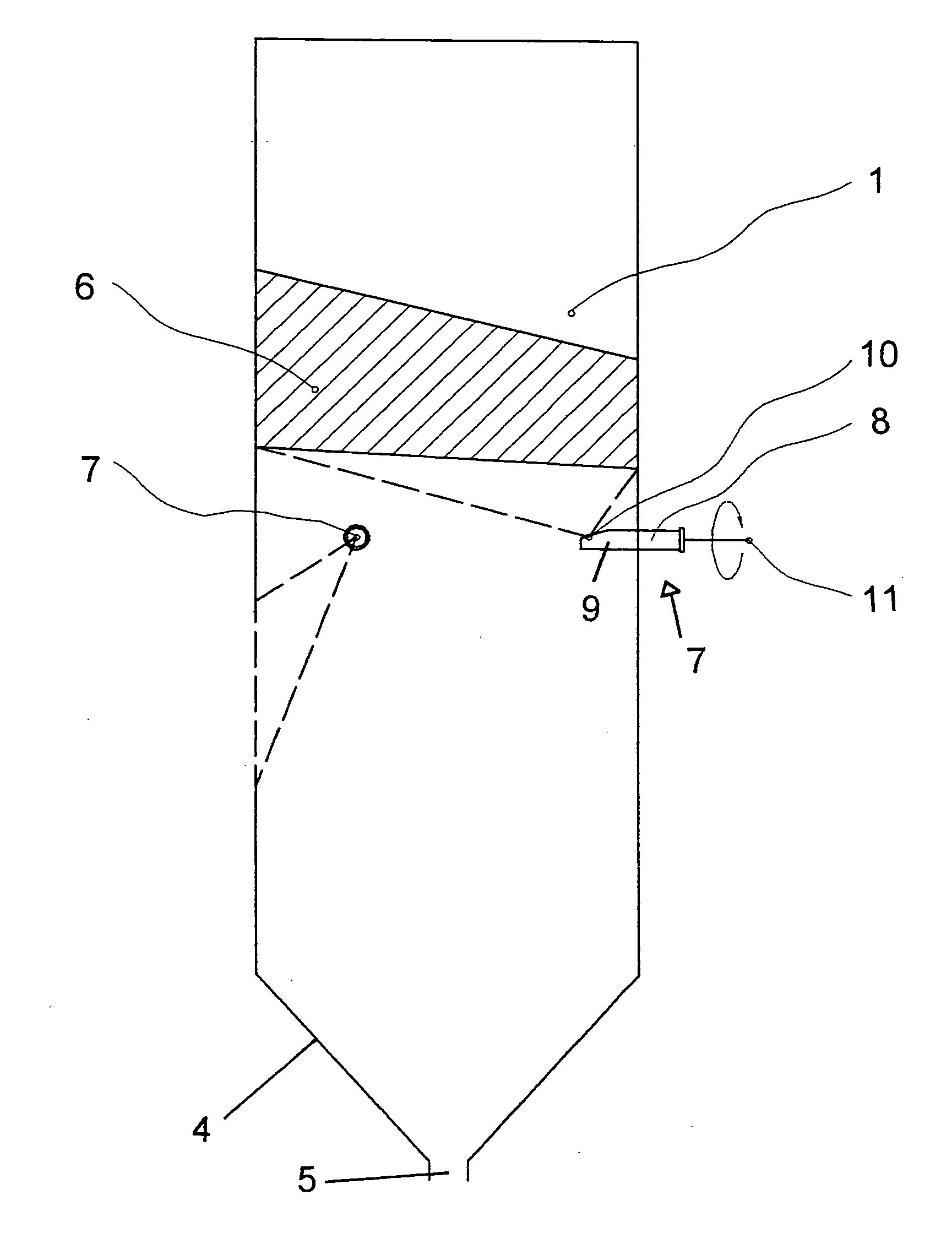
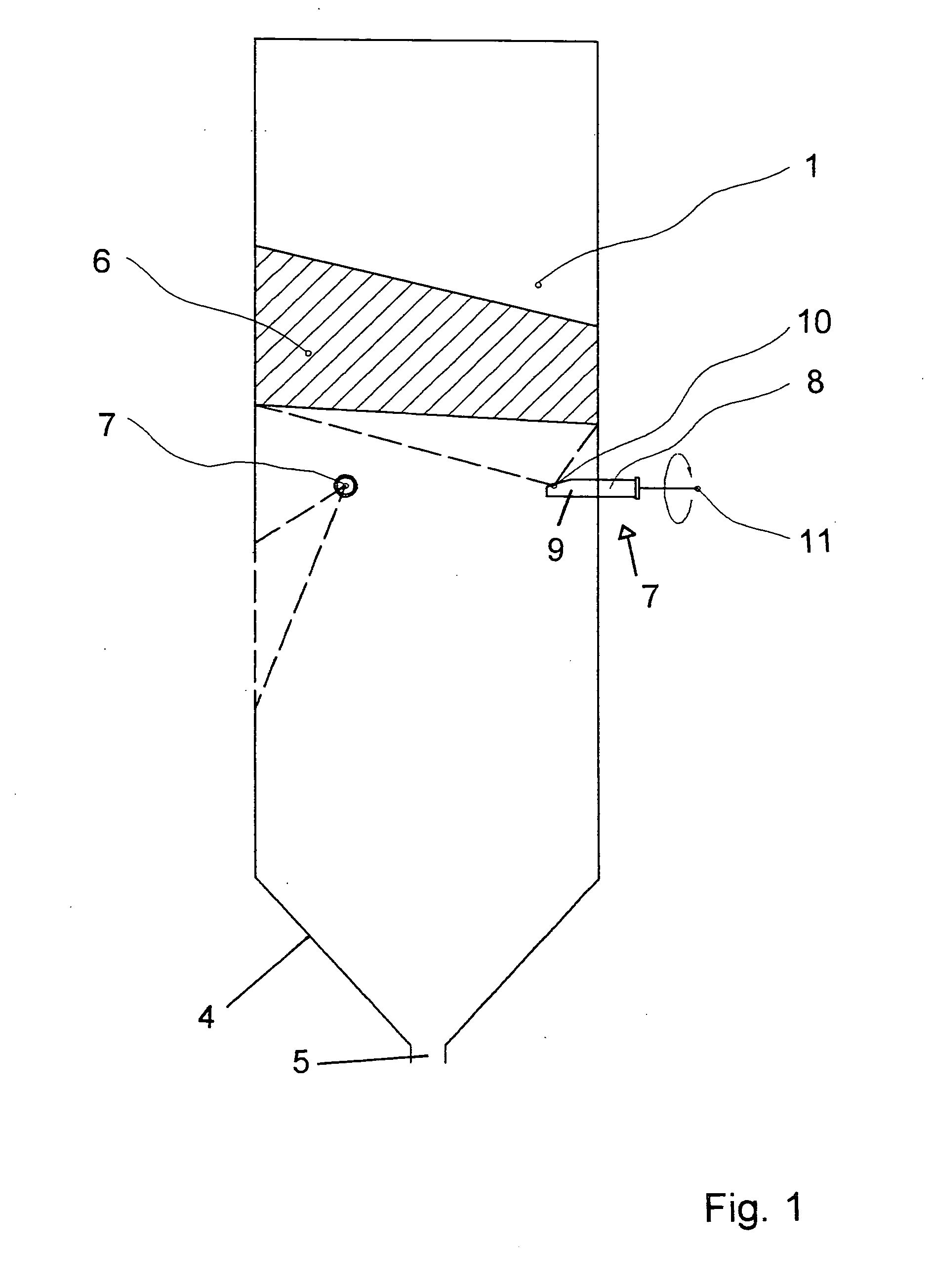
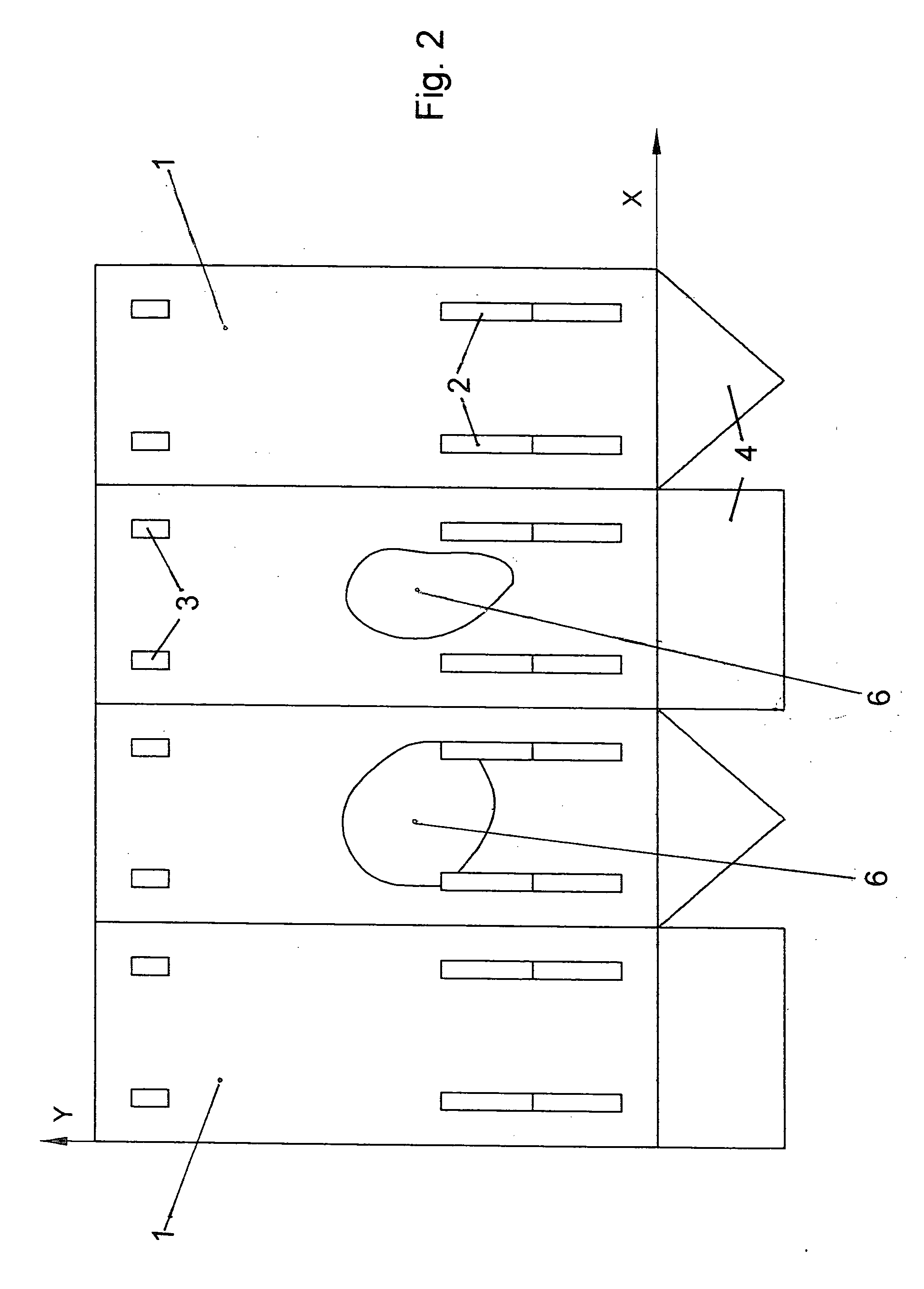
[0017]The combustion chamber or furnace of a power plant boiler fired with coal dust is delimited by walls 1 in which are provided burner openings 2 for receiving burners as well as openings 3 for the discharge of the secondary air. The walls 1 of the furnace are composed of tubes that are welded together in a gas tight manner by ribs or fins. The furnace has a rectangular cross-section, and ends in a funnel 4 having a discharge slot 5 for the removal of ash. At the upper end, the furnace merges with a non-illustrated flue for flue gas. The tubes of the walls 1 of the furnace act as evaporators, and water and water vapor flow through them as working or cooling medium.

[0018]A portion of the solid particles that remain behind upon combustion of the coal dust are carried along by the flue gas that rises in the furnace. Depending upon the quantity and composition of the solid particles, more or less large surfaces of deposits or incrustations 6 form on the inner side of the walls 1 due ...


PUM


Abstract

Method and apparatus for monitoring formation of deposits of solid particles from flue gas onto furnace walls formed of welded-together tubes through which cooling medium flows. For the entire surface of the walls, the exact surface temperature is detected with infrared cameras, offset by 90° relative to one another, via a thermal image obtained of a surface development of the furnace. This exact surface temperature is compared with the temperature of the cooling medium from measurement locations. Individual images from the cameras are composed to form an overall development of the inner surface of the furnace walls. The coordinates of the deposits on the walls are determined from the overall development, and the thickness of the deposits is determined from the temperature comparison.

Description

[0001]The instant application should be granted the priority date of Aug. 29, 2005, 2005 the filing date of the corresponding German patent application 10 2005 041 004.9.BACKGROUND OF THE INVENTION[0002]The invention relates to a method and apparatus for monitoring the formation of deposits caused by depositions of solid particles from a hot, dust-laden flue gas onto the walls of a rectangular furnace of a boiler by taking an infrared image of the walls with the aid of an infrared camera, wherein the walls are formed by tubes that are tightly welded together and through which a cooling medium flows.[0003]When boilers are fired with solid fuel, on the flue gas side deposits are formed on the heating surfaces due to the deposition of solid particles, for example ash. Due to their heat-insulating effect, such deposits on the heating surfaces hinder the transfer of heat from the flue gas to the working medium (water / water vapor) in the tubular walls of the heating surfaces, thus reducin...

Claims


Application Information

Patent Timeline
IPC IPC(8): G01N25/00G01J5/00
CPCF23J3/02F23M5/08F23M11/04F22B37/56F22B37/48
Inventor KOSCHACK, RALFHOVEN, GUNTERSOBOTTA, BERNHARD
Owner DIPL ING INGO RADUNZ
Why Eureka
Try Eureka