
Staged Membrane Oxidation Reactor System

a membrane oxidation and reactor technology, applied in the direction of gas-gas reaction process, separation process, bulk chemical production, etc., can solve the problems of membrane module upper temperature limit, membrane material and membrane module components can be subjected to significant mechanical stresses, and membrane modules can be damaged. , the effect of membrane degradation

Inactive Publication Date: 2008-12-11
AIR PROD & CHEM INC
View PDF34 Cites 70 Cited by
  • Summary
  • Abstract
  • Description
  • Claims
  • Application Information

AI Technical Summary

Benefits of technology

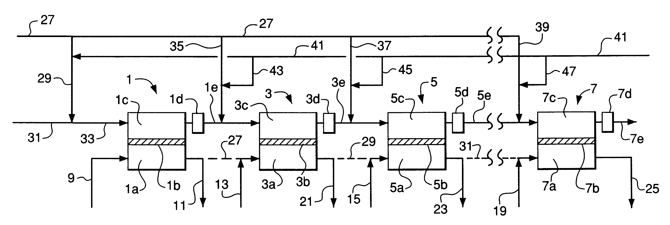
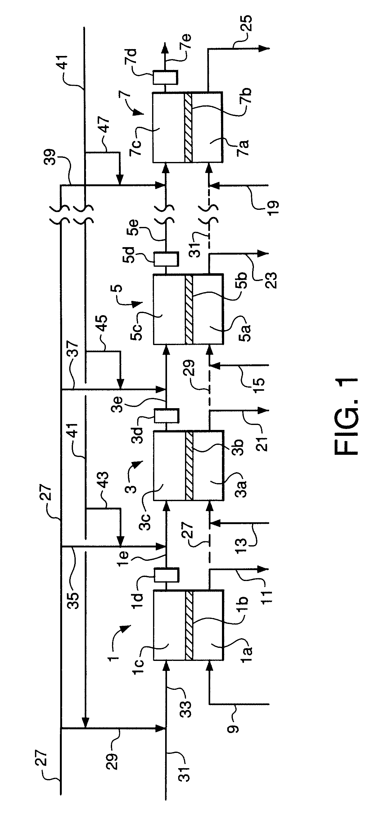
[0006]One embodiment of the invention relates to an ion transport membrane oxidation system comprising (a) two or more membrane oxidation stages, each stage comprising a reactant zone, an oxidant zone, one or more ion transport membranes separating the reactant zone from the oxidant zone, a reactant gas inlet region, a reactant gas outlet region, an oxidant gas inlet region, and an oxidant gas outlet region; (b) an interstage reactant gas flow path disposed between each pair of membrane oxidation stages, wherein

Problems solved by technology

The ceramic membrane material and the components of the membrane modules can be subjected to significant mechanical stresses during normal steady-state operation and especially during unsteady-state startup, shutdown, and upset conditions.
In addition, membrane modules have upper temperature limits above which membrane degradation and / or module damage may occur.
The potential operating problems caused by these phenomena may have a significant negative impact on the conversion efficiency and membrane operating life of the system.

Method used


Image

  • Staged Membrane Oxidation Reactor System
  • Staged Membrane Oxidation Reactor System
  • Staged Membrane Oxidation Reactor System

Examples


example 1

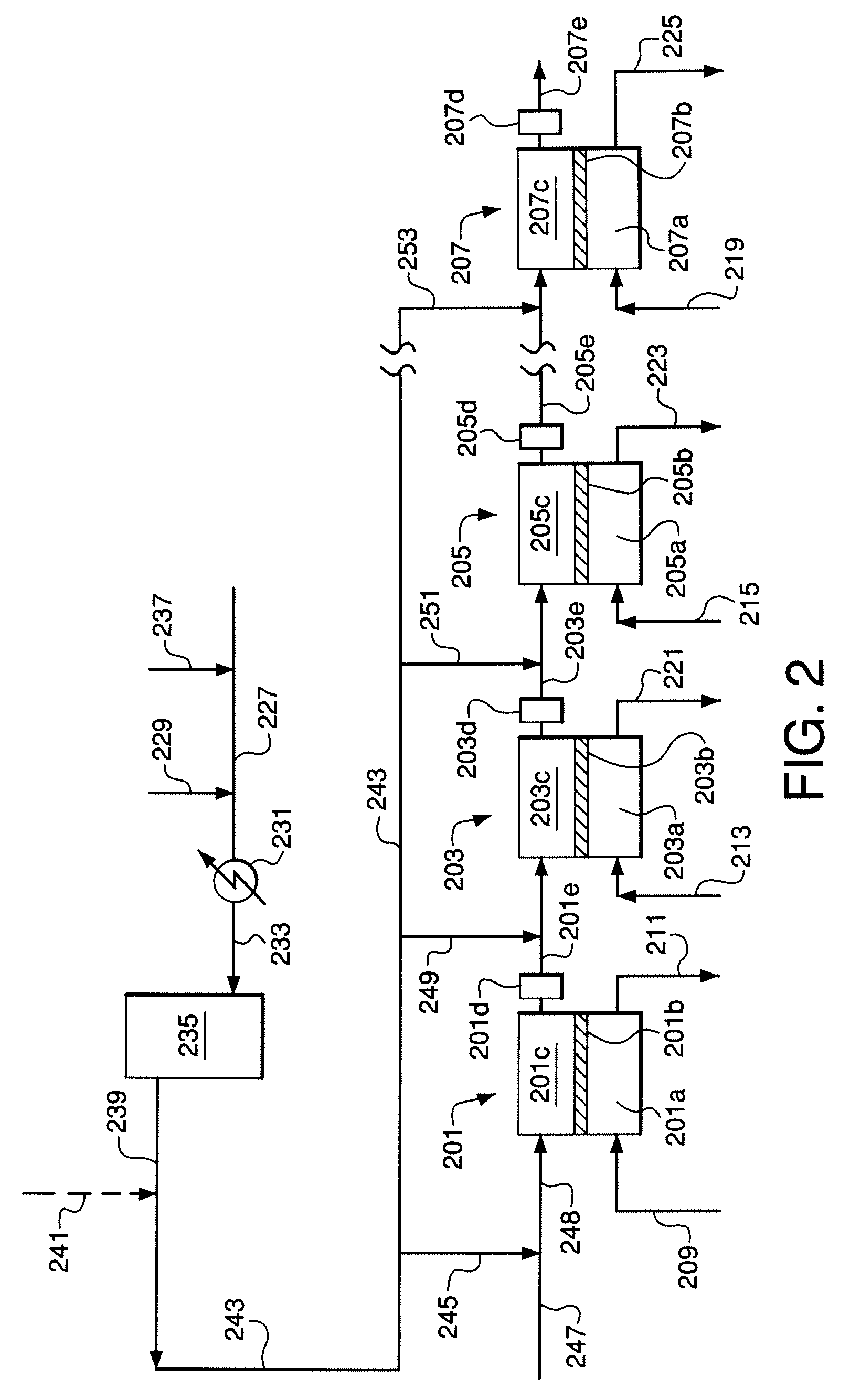
[0116]An embodiment of the invention similar to FIGS. 2 and 3 was simulated using the process simulator Aspen Plus™ from Aspen Technology, Inc. The simulation utilized 100 membrane reactor stages in series wherein the reactant gas feed is divided into ten portions (not necessarily equal) and each portion is divided into ten equal sub-portions. Each sub-portion is fed to the inlet of a corresponding stage wherein the sub-portion to the first stage is mixed with steam and each of the remaining sub-portions is provided as a reactant interstage feed gas that is mixed with a corresponding interstage reactant gas stream.

[0117]The following specific process features and parameters were used in the simulation:[0118]Total sum of oxygen permeation in all stages is 1000 kgmol / hr with an evenly-distributed oxygen flux of 10 kgmol / hr in each stage.[0119]Overall steam-to-carbon molar ratio is 1.5 in the reactant feed to the system wherein the steam-to-carbon ratio is defined as total water divide...

example 2

[0128]Operation of the system of Example 2 was simulated using the same simulation method and the same specific process features and parameters as in Example 1, except that catalyst is not used within the membrane modules. Instead, an adiabatic catalyst bed is provided at the exit of each stage (see FIGS. 1 and 2) to equilibrate the steam reforming, carbon dioxide reforming, and water-gas shift reactions. 2219.7 kgmol / hr steam is preheated to 860° C. and introduced to the first reactor stage. 2135.8 kgmol / hr natural gas, 67.0 kgmol / hr hydrogen, and 1109.9 kgmol / hr steam are mixed and preheated to 510° C., pre-reformed in an adiabatic pre-reformer reactor, and withdrawn from the adiabatic pre-reformer reactor at 474° C. The pre-reformed mixture is divided into the portions given in Table 3.

TABLE 3Reactant Feed Gas Distribution for Example 2Flow toDistribution of Pre-reformedStage GroupReactant Feed to Stage GroupsPortionkgmol / hr%Stages 1 through 101335.19.7Stages 11 through 202327.89...

example 3

[0131]Operation of the system of Example 3 was simulated using the same simulation method and the same specific process features and parameters as in Example 1. 1505.3 kgmol / hr natural gas, 47.3 kgmol / hr hydrogen, and 782.2 kgmol / hr steam are mixed and preheated to 510° C. The heated mixture is pre-reformed in an adiabatic pre-reformer reactor and exits the adiabatic pre-reformer reactor at 474° C. A stream of recycled offgas from a Fischer-Tropsch synthesis reactor at 2631.5 kgmol / hr and 38° C. having a composition of 38.1% hydrogen, 11.7% methane, 28.8% carbon dioxide, 19.10% carbon monoxide, 0.3% water, and 2.0% nitrogen is mixed with the pre-reformed reactant gas. The resulting mixed reactant feed gas at 282° C. is divided and distributed to the 100 ITM stages for temperature control, and the amount of recycle gas is used to control the H2 / CO ratio in the synthesis gas product from the reactor system. The mixed reactant feed gas is divided into portions as given in Table 5.

TABLE...


PUM


Abstract

Ion transport membrane oxidation system comprising (a) two or more membrane oxidation stages, each stage comprising a reactant zone, an oxidant zone, one or more ion transport membranes separating the reactant zone from the oxidant zone, a reactant gas inlet region, a reactant gas outlet region, an oxidant gas inlet region, and an oxidant gas outlet region; (b) an interstage reactant gas flow path disposed between each pair of membrane oxidation stages and adapted to place the reactant gas outlet region of a first stage of the pair in flow communication with the reactant gas inlet region of a second stage of the pair; and (c) one or more reactant interstage feed gas lines, each line being in flow communication with any interstage reactant gas flow path or with the reactant zone of any membrane oxidation stage receiving interstage reactant gas.

Description

STATEMENT REGARDING FEDERALLY SPONSORED RESEARCH OR DEVELOPMENT[0001]This invention was made with government support under Contract Number DE-FC26-97FT96052 between Air Products and Chemicals, Inc. and the U.S. Department of Energy. The Government has certain rights to this invention.BACKGROUND OF THE INVENTION[0002]The permeation of oxygen ions through ceramic ion transport membranes is the basis for the design and operation of high-temperature oxidation reactor systems in which permeated oxygen is reacted with oxidizable compounds to form oxidized or partially-oxidized reaction products. The practical application of these oxidation reactor systems requires membrane assemblies having large surface areas, flow passages to contact oxidant feed gas with the oxidant sides of the membranes, flow passages to contact reactant feed gas with the reactant sides of the membranes, and flow passages to withdraw product gas from the permeate sides of the membranes. These membrane assemblies may ...

Claims


Application Information

Patent Timeline
IPC IPC(8): C01B3/24
CPCB01J12/007C01B2210/0046B01J2219/00006B01J2219/0004B01J2219/00065B01J2219/00103C01B3/38C01B13/0251C01B2203/0233C01B2203/0238C01B2203/0244C01B2203/0283C01B2203/1241C01B2203/127C01B2203/142B01J19/2475Y02P20/52B01J12/00B01J19/00
Inventor REPASKY, JOHN MICHAELCAROLAN, MICHAEL FRANCISSTEIN, VANERIC EDWARDCHEN, CHRISTOPHER MING-POH
Owner AIR PROD & CHEM INC
Learn More