Method and apparatus for lengthening a pipe string and installing a pipe string in a borehole

a pipe string and pipe string technology, applied in the direction of wellbore/well accessories, manufacturing tools, etc., can solve the problems of inability to meet the requirements of drilling, completion and production activities, and the practicality of conventional welding of long pipe string suitable for use in connection with drilling, and achieve the effect of preventing unwanted oxidation and preventing oxidation of heated material

Inactive Publication Date: 2008-12-11
FRANKS INT
View PDF48 Cites 35 Cited by
  • Summary
  • Abstract
  • Description
  • Claims
  • Application Information

AI Technical Summary

Benefits of technology

[0018]In another embodiment, an internal clamp may be used either in place of or with external clamps to align the pipe segment with the pipe string, either to form an abutment or to form a gap substantially smaller than the diameter of the rotating friction stir welding probe. The internal clamp may be inserted into the bore of the pipe segment and positioned to straddle the abutment or the gap between the lower end of the pipe string and the proximal end of the pipe segment. The internal clamp is expandable to grip the pipe string and the pipe segment to maintain the abutment or the gap and may also be designed to resist separation of the pipe segment from the pipe string during friction stir welding. An internal clamp may also be coupled to a source of inert gas for displacing air from the vicinity of the friction stir welded joint to prevent unwanted oxidation of the material that is heated by the friction stir welding process.
[0019]In another embodiment, an internal alignment device may be used to provide reinforcement to the wall of the pipe segment and the pipe string to resist deformation under the large forces applied by the friction stir welding probe as it is forcibly inserted into the abutment or the gap, and as it is forced into the abutment or the gap to join the pipe segment to the pipe string. The internal alignment device may also be coupled to a source of inert gas for displacing air from the vicinity of the friction stir welded joint to prevent oxidation of heated material. The internal alignment device may be especially useful in joining pipe segments and pipe strings having a thin pipe wall that might otherwise deform under the load applied by the friction stir welding machine.
[0020]In another embodiment of the method of the present invention, the lower end of the pipe segment and the proximal end of the pipe string may be formed for mating engagement to resist radial movement of one relative to the other during friction stir welding. For example, the weld bevels on the lower end of the pipe segment may be tapered to form the radially exterior surface of a truncated conical frustum, and the weld bevels on the proximal end of the pipe string may be reverse tapered to form the radially interior surface of a truncated conical frustum so that the lower end of the pipe segment may be received into the proximal end of the pipe string to form an interface that is not purely horizontal relative to the axis of the workpieces. This type of mating interface is generally self-aligning; that is, the interface tends to secure the pipe segment and the pipe string in the aligned condition.
[0026]The method of the present invention uses the friction stir welding process to provide a pipe string comprising a plurality of joined pipe segments, the pipe string having a generally uniform wall thickness at the welded connections that is substantially the same thickness as the adjacent pipe wall, and highly reliable for expansion, along with the non-welded portions of the pipe string, to form an expanded pipe string having a larger diameter.
[0030]The use of friction stir welding with the present invention to join pipe segments to a pipe string offers many advantages that cannot be achieved by using conventional welding. Friction stir welding eliminates many safety hazards associated with conventional welding such as open ignition sources, toxic fumes, weld spatter, transportation of and connections to bottled or tanked industrial gasses, and visual sensitivity of humans to the arcs produced during conventional welding. Also, unlike with conventional welding, the entire length of the pipe string does not become a part of an electrical circuit with friction stir welding. Other costly and time-consuming activities associated with conventional welding are also eliminated, such as beveling of surfaces to be welded, weldor training and skills certifications, preheating of workpieces to a minimum temperature, and post-weld cooling of workpieces to a maximum temperature prior to loading.

Problems solved by technology

Except for drive pipe and conductor casing installed near the surface of a well, welding has not been practically used for forming long pipe strings for use in drilling, production or completion activities.
Conventional welding of long pipe strings suitable for use in connection with drilling, completion and production activities is not practical because the pipe string, which is generally vertically suspended at the suspending device, must be formed by joining one vertical add-on pipe segment (or stand) at a time to lengthen the pipe string, lowering the lengthened pipe string through the rig floor, and then repeating the process until the pipe string reaches its desired length.
Conventional welding limits the rate of fabrication of a pipe string because, compared to assembling a pipe string using threaded connections, conventional welding is a slow process that may take up to 60 minutes or more to complete the weld required at each individual pipe joint, and also because the vertical orientation of the proximal end of the pipe string, and of the add-on pipe segment to be conventionally welded to the pipe string, allows welding of only one pipe joint at a time.
Since a threaded pipe connection can be made-up much faster than a non-threaded connection can be conventionally welded, these limitations make the assembly and installation of a pipe string by conventional welding uneconomical.
Another problem with the use of conventional welding for forming and installing a pipe string in a borehole is the difficulty in obtaining welded pipe connections that are free of weld defects and resistant to failure.
Conventionally welded connections include heat-affected zones (“HAZ's”) that may, without proper stress relieving, adversely affect the strength and reliability of the welded joint.
Although conventionally welded joints may be stress relieved to eliminate detrimental HAZ's, stress relieving would only increase the total amount of time consumed in forming each pipe joint.
Conventional connections consume a substantial amount of radial space due to the radially overlapping configuration of threaded connections.
Also, for expandable pipe strings, conventional threaded connections make expansion more difficult since threaded sleeve connections offer substantially more resistance to forced radial expansion than the portions of the pipe wall between the threaded ends of the pipe.
Threaded connections that offer good sealing performance in their original state do not reliably maintain the seal after being forcibly expanded or after being installed in a high-temperature service environment.
On the other hand, threaded connections may not provide a fluid-tight seal, especially after being expanded, and leaks at the joints may lead to undesirable consequences.
Another drawback to using threaded connections to form and install expandable pipe strings involves the use of expansion tools to expand the pipe string within the borehole.
The difficulties presented by using conventional threaded connections for expandable pipe strings prompted some to experiment with different welding techniques for joining pipe segments to form a pipe string.
However, safety does not generally permit conventional welding techniques requiring an open ignition source at or near the borehole where hydrocarbon gases could be ignited.
For the same reasons, other newer forms of welding such as electrical resistance welding, radial friction welding, flash welding (U.S. Pat. No. 6,935,429), metallurgical bonding (U.S. Pat. No. 6,860,420), explosive welding (U.S. Pat. No. 6,953,141), amorphous bonding (U.S. Pat. No. 6,078,031), forge welding (U.S. Pat. No. 7,181,821) and laser welding (U.S. Pat. No. 7,150,328) are also generally unacceptable or impractical.
These other newer forms of welding have individual drawbacks associated with each technique including, but not limited to, electrical spark generation, production of toxic fumes, visual limitations due to involved arc flash, other sources of ignition, workpiece pre-heating requirements, equipment limitations (cost, size, etc), environmental restrictions (rain, moisture, wind, humidity, etc.), lack of reliable weld quality, repeatability and speed of weld production.
Therefore, these other newer forms of welding, like conventional welding techniques, are too risky to use near a borehole.

Method used


Image

  • Method and apparatus for lengthening a pipe string and installing a pipe string in a borehole
  • Method and apparatus for lengthening a pipe string and installing a pipe string in a borehole
  • Method and apparatus for lengthening a pipe string and installing a pipe string in a borehole

Examples


Embodiment Construction

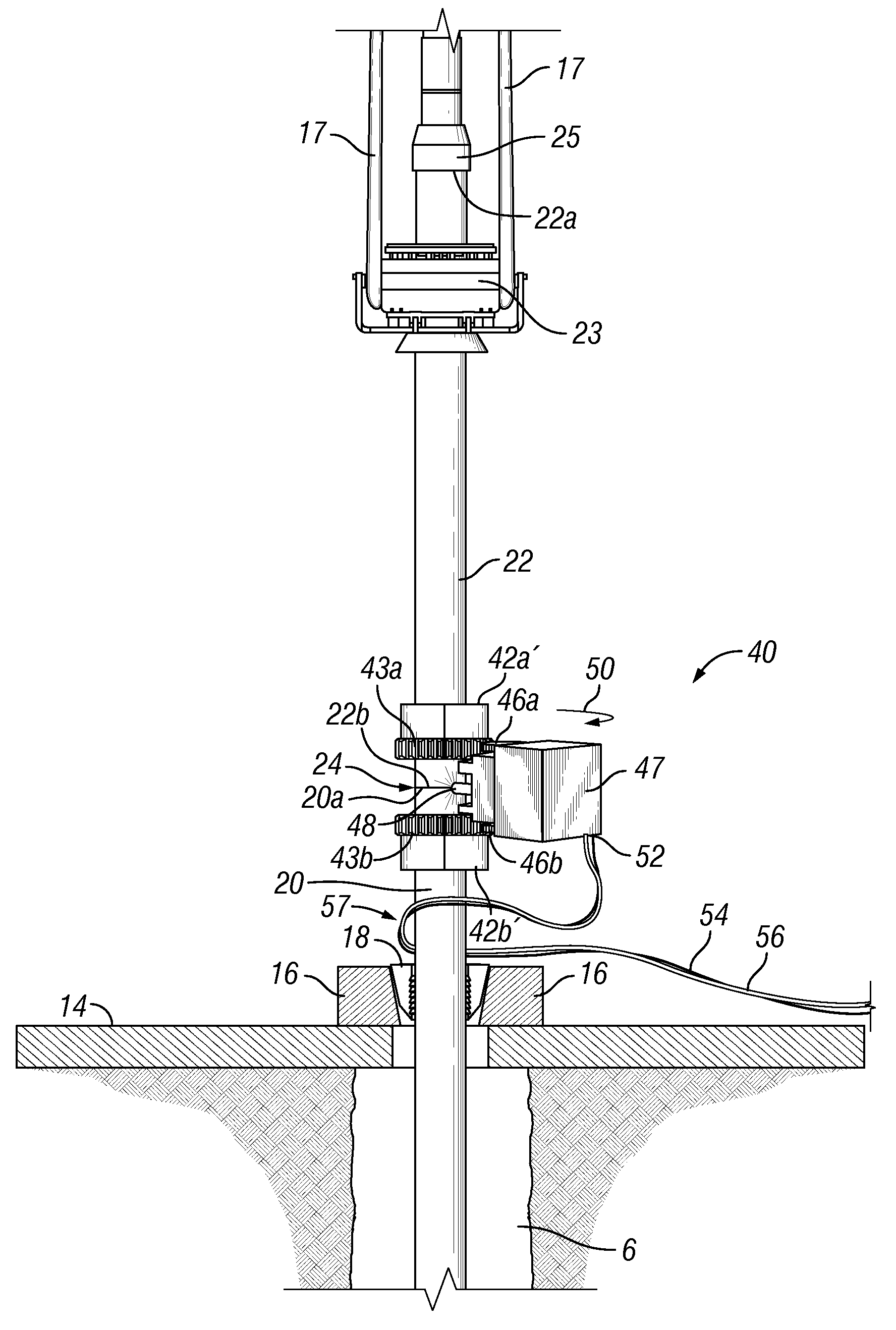
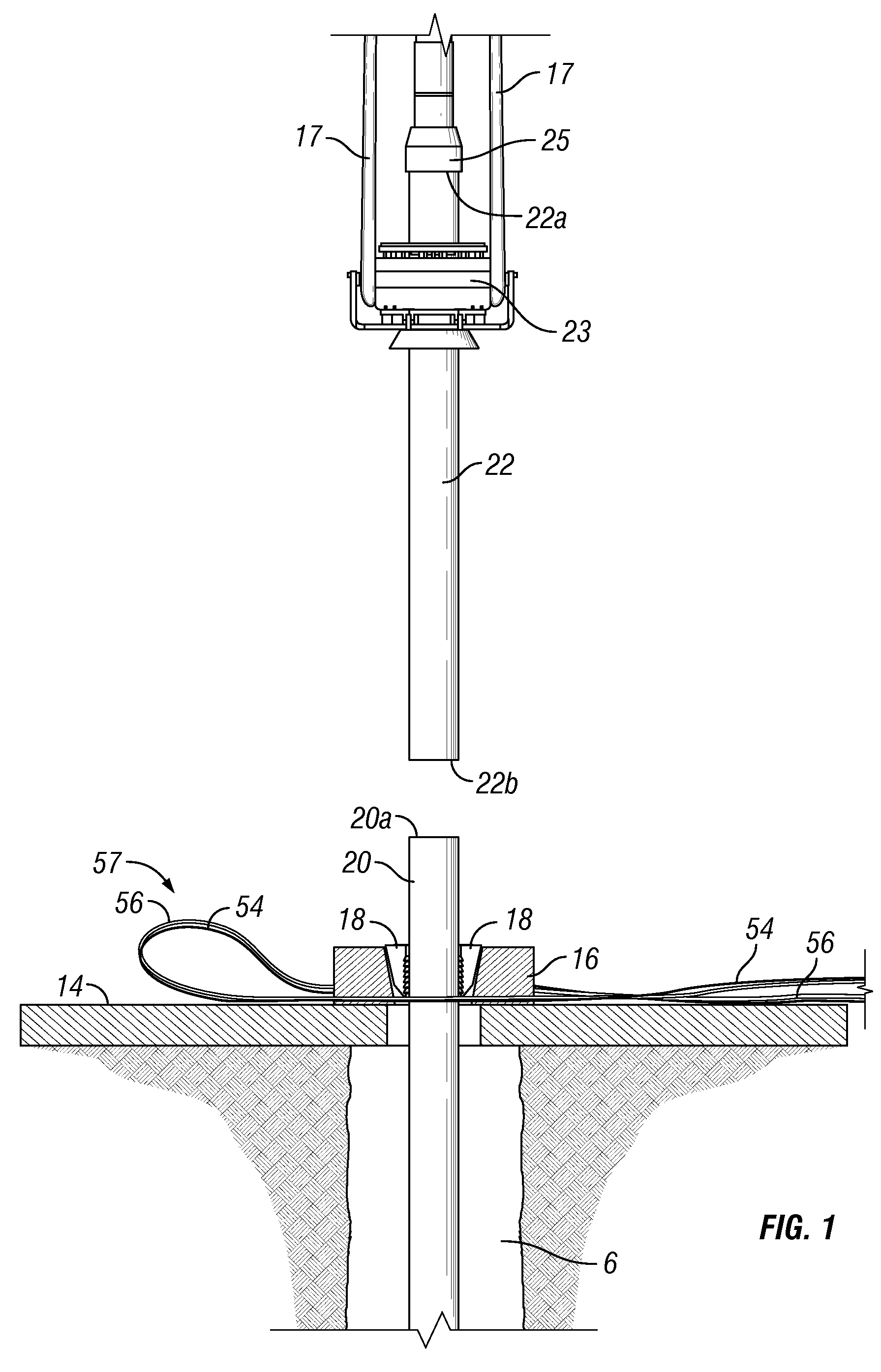
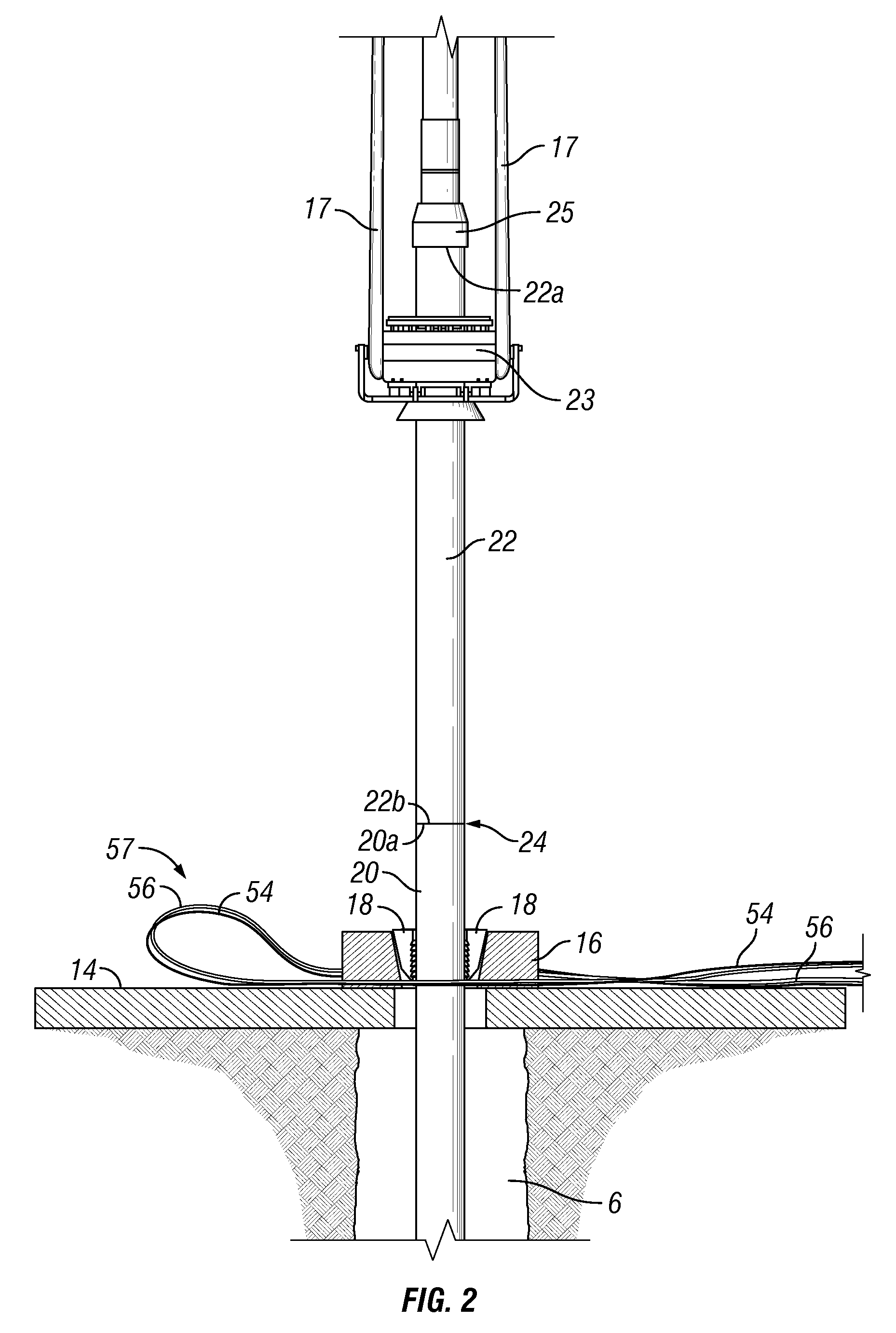
[0042]FIG. 1 is a partial cross-section view of a rig floor 14 supporting a spider 16 having slips 18 that engage and suspend a pipe string 20 within a borehole 6 beneath a generally linear pipe segment 22 that is suspended over the rig floor by an externally-gripping elevator 23. Power bundle 57, having a first portion 56 (that crosses in front of the spider 16 that is shown in cross-section) and a second portion 54, is shown generally circumscribing the pipe string 20. The string elevator 23 is suspended from a block (not shown in FIG. 1) using bails 17, and the string elevator 23 may be controllably raised and lowered using a drawworks (not shown in FIG. 1) that supports the block. The pipe segment 22 has an upper end 22a positioned above the string elevator 23 and a lower end 22b disposed toward the rig floor 14. The pipe segment 22 is generally positionable using the drawworks and the string elevator 23 for being abutted or nearly abutted against the proximal end 20a of the pip...


PUM

PropertyMeasurementUnit
lengthaaaaaaaaaa
lengthaaaaaaaaaa
diameteraaaaaaaaaa

Abstract

The present invention generally relates to a method and an apparatus for connecting an add-on pipe segment to a pipe string to lengthen the pipe string using friction stir welding. The pipe string is suspended in a borehole using a spider or some other pipe suspending device, and the lower end of the pipe segment is brought into an abutting or nearly abutting relationship with the proximal end of the pipe string positioned above the pipe suspending device and above the rig floor. The friction stir welding machine is brought to well center to weld the abutment or gap between the pipe segment and the pipe string and join the pipe segment to the pipe string to lengthen the pipe string. In one aspect, the method includes friction stir welding an expandable pipe segment to an expandable pipe string to form a lengthened expandable pipe string. The pipe segment may be comprised of two or more pipe segments that have been friction stir welded or conventionally welded to form a pipe stand. After friction stir welding to lengthen the pipe string, the lengthened pipe string is lowered into the borehole and the proximal end of the lengthened pipe string is favorably positioned to abut or nearly abut a new add-on pipe segment for friction stir welding at the resulting abutment or gap. The friction stir welding process provides a highly reliable pipe joint for expansion.

Description

BACKGROUND OF THE INVENTION[0001]1. Field of the Invention[0002]The present invention relates to apparatus and methods for lengthening a pipe string using friction stir welding and for installing a friction stir welded pipe string in a borehole. Specifically, the present invention relates to using friction stir welding to join a pipe segment to a pipe string that is suspended from a rig by a suspending device such as a spider, a landing table, a collar load support device, or other devices known in the art for suspending a pipe string from a rig.[0003]2. Description of the Related Art[0004]Conventional pipe strings that are installed in a borehole generally comprise pipe segments, typically 30 to 60 feet in length, threadedly connected to form a pipe string that can extend up to 10,000 feet or more. The pipe segments of conventional pipe strings are connected using threaded connections including an internally threaded sleeve that threadedly receives a first externally threaded pipe ...

Claims


Application Information

Patent Timeline
Patent Type & Authority Applications(United States)
IPC IPC(8): E21B19/16
CPCB23K20/1225B23K20/14B23K2201/06B23K2203/04E21B19/16E21B43/10E21B43/103B23K2101/06B23K2103/04
Inventor MALLENAHALLI, PRADEEP KUMARDOMEC, BRENNAN SCOTTWEBRE, CHARLES MICHAELVEVERICA, MARK ALANWHEELER, JOHN FLETCHER
Owner FRANKS INT
Why Eureka
Try Eureka