

Retinal reflection generation and detection system and associated methods
a detection system and retinal reflection technology, applied in the field of optical tracking systems, can solve the problems of difficult to achieve a completely “on/off” data set, sharpness of the pupil boundary, etc., and achieve the effect of optimizing the intensity of the beam reflected and effectively using undilated eyes
- Summary
- Abstract
- Description
- Claims
- Application Information
AI Technical Summary
Benefits of technology
Problems solved by technology
Method used
Image

Examples
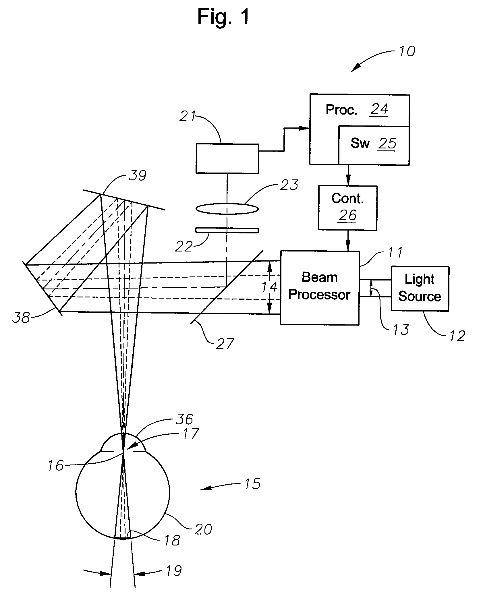
embodiment 30
[0026]In the embodiment 30 of FIG. 2, an imaging lens 35 is positioned downstream of the small aperture 34, for imaging the small aperture 34 on a cornea 36 of the eye 15. The altering means comprises a variable-size aperture 37 downstream of the imaging lens 35, for spatially filtering radiation emerging from the imaging lens 35 to control the spot size at the retina 20.
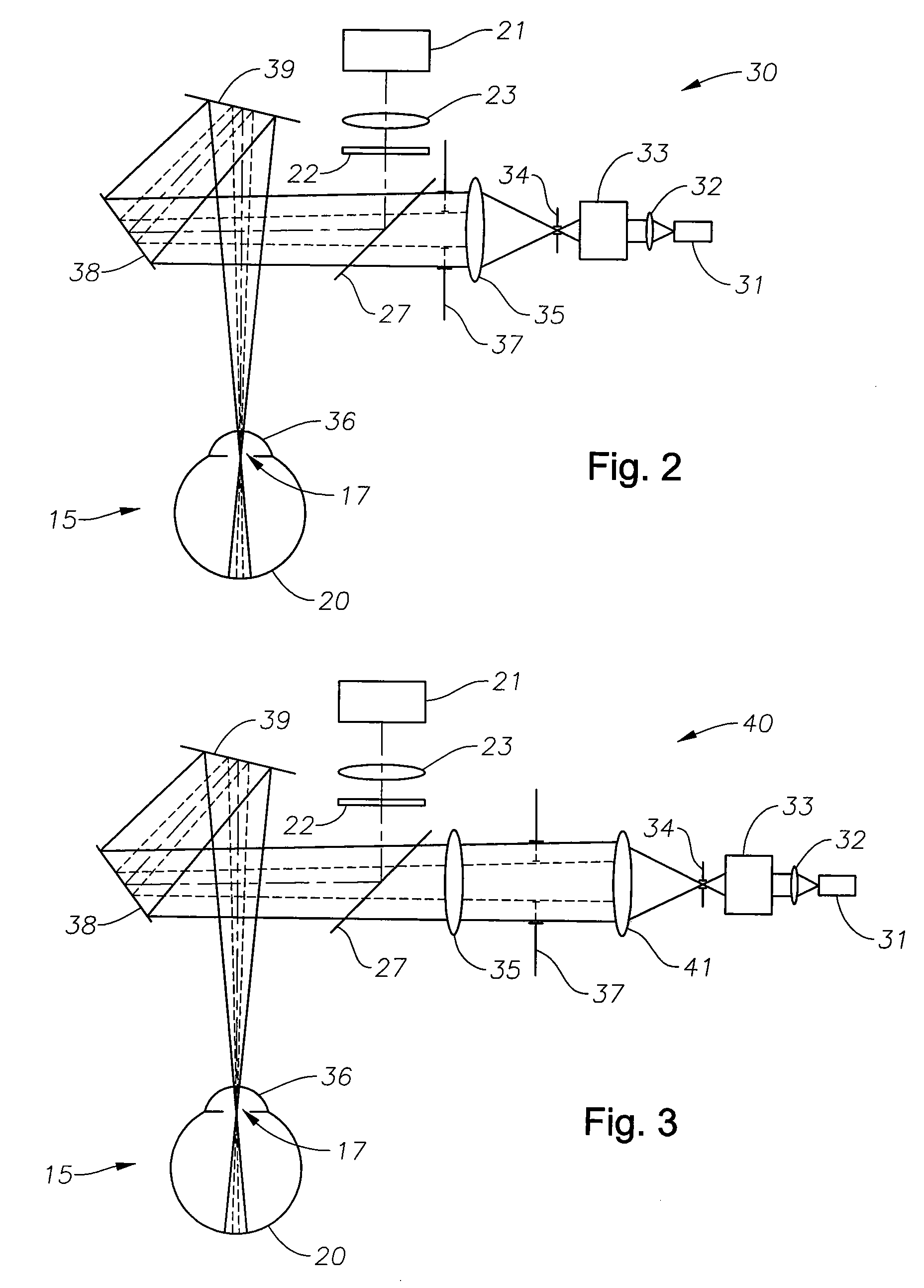
embodiment 40
[0027]In the embodiment 40 of FIG. 3, a second collimation lens 41 is positioned downstream of the small aperture 34, and the variable-size aperture 37 is positioned downstream of the collimation lens 41, for spatially filtering radiation emerging from the collimation lens 41 to control the spot size at the retina. An imaging lens 35 is provided downstream of the variable-size aperture 37, for focusing an incoming beam on the cornea 36. Since the distance between the second collimation lens 41 and the imaging lens 35 has essentially no impact on system performance, the system 40 can provide a long optical path if desired, depending upon the design of the entire system.
[0028]Exemplary simulation results are illustrated in FIGS. 4A-4I, showing the simulated pupil glow images for a model eye with +5D refractive error, 8 mm pupil size, and either 0° or 4° eye rotation. The retina is illuminated by a beam with variable spot size. Table 1 presents the measured pupil size from the pupil gl...
PUM
 Abstract
Description
Claims
Application Information