Cryo-applicator cross-section configuration

a technology of cryo-applicators and cross-sections, which is applied in the field of configuration of cryo-applicators, can solve the problems of low ablation temperature, insufficient cryo-ablation tissue efficiency, and large latent heat transfer, and achieves low supply pressure, low return pressure, and greater flow capacity.

Active Publication Date: 2008-12-11
CRYOCOR
View PDF27 Cites 39 Cited by
  • Summary
  • Abstract
  • Description
  • Claims
  • Application Information

AI Technical Summary

Benefits of technology

[0014]To cool the cryo-catheter's distal tip, a two-part refrigerant supply line is disposed in the central lumen. More specifically, the supply line includes a high pressure supply tube and a flow restricting tube (e.g. capillary tube). Structurally, the capillary tube is attached to and extends from a distal end of the high pressure supply tube. In the operation of the cryo-catheter, a regulated flow of liquid refrigerant is introduced into the proximal end of the high pressure supply tube. With this arrangement, the refrigerant traverses the supply tube, passes through the capillary tube and then outflows into an expansion chamber at the cryo-catheter's distal tip. Expanded refrigerant is then exhausted from the chamber through a low pressure return line that is established in the void spaces between the outer wall of the supply line and the inner wall of the catheter body. It is important to note that the exact nature and dimensions of these void spaces varies along the length of the cryo-catheter. Specifically, at each location along the length of the catheter, the available void space will depend on the size and extent of other catheter structures (i.e. accessories) that are present in the central lumen at that particular location. These catheter accessories can include, but are not necessarily limited to, pull wires, sheath springs, sheath spring guide tubes, thermocouple wires, electrode wires and pressure measurement tubes. For the cryo-catheter, each of these accessories extends through some or all of the length of the catheter.
[0015]The dimensions of the refrigerant flow paths are functionally significant and typically must be sized with several operational objectives in mind. Specifically, these dimensions control the pressures and flow rates at critical points along the refrigerant flow path. In greater detail, the pressure within the high pressure supply tube must be sufficient to maintain the refrigerant in a liquid state throughout the length of the supply tube. On the other hand, the pressure in the expansion chamber must be sufficiently low to allow for full refrigerant vaporization within the chamber. As a consequence, the capillary tube must create the necessary pressure reduction between the high pressure supply tube and the low pressure expansion chamber.
[0016]In addition to the requirements described above, the refrigerant pressures and flow path dimensions are generally designed to avoid operation of the cryo-catheter in a refrigerant limited condition. This condition is typically characterized as having a relatively low supply pressure for refrigerant entering the supply tube together with a relatively low return pressure. In the refrigerant limited condition, the catheter is typically unable to achieve the lowest possible cryoablation temperature at the catheter's distal tip. Quantitatively, the expansion chamber is generally maintained at a pressure of approximately 1 atm. In addition, the accessories and fluid supply line are arranged to leave a portion of a first cross-sectional area void in the articulation segment and leave a portion of said second cross-sectional area void in the braided segment. These voids establish a return path for a flow of gaseous refrigerant through the central lumen. Preferably, the cryo-catheter is configured with the second cross-sectional area void being greater than about thirty percent of the first cross-sectional area. As a consequence, the return path in the articulation segment has a somewhat greater flow capacity than the return path in the braided segment. With this interactive cooperation of structure, refrigerant is maintained as a liquid in the high pressure supply tube while maintaining the expansion chamber at a pressure of about 1 atm. to ensure that the cryo-catheter does not operate in a refrigerant limited condition.

Problems solved by technology

A low ablation temperature, however, is typically not sufficient to efficiently cryoablate tissue.
For some fluids, this latent heat transfer can be considerable.
This notion, however, has it limits.
This increased flow rate, however, creates additional increases in the return pressure (i.e. back pressure) that will result in a detrimental increase in the boiling point temperature of the refrigerant.
Refrigerant flow in this range is said to be “refrigeration limited.” On the other hand, for relatively high mass flow rates, increases in the mass flow rate actually cause the temperature of the refrigerant to rise.

Method used


Image

  • Cryo-applicator cross-section configuration
  • Cryo-applicator cross-section configuration
  • Cryo-applicator cross-section configuration

Examples


Embodiment Construction

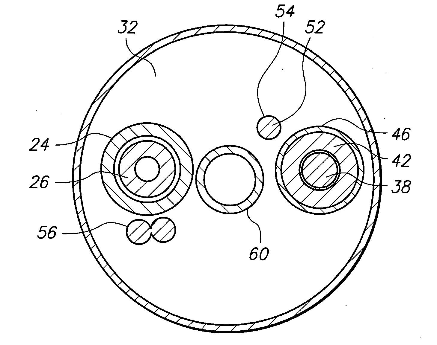
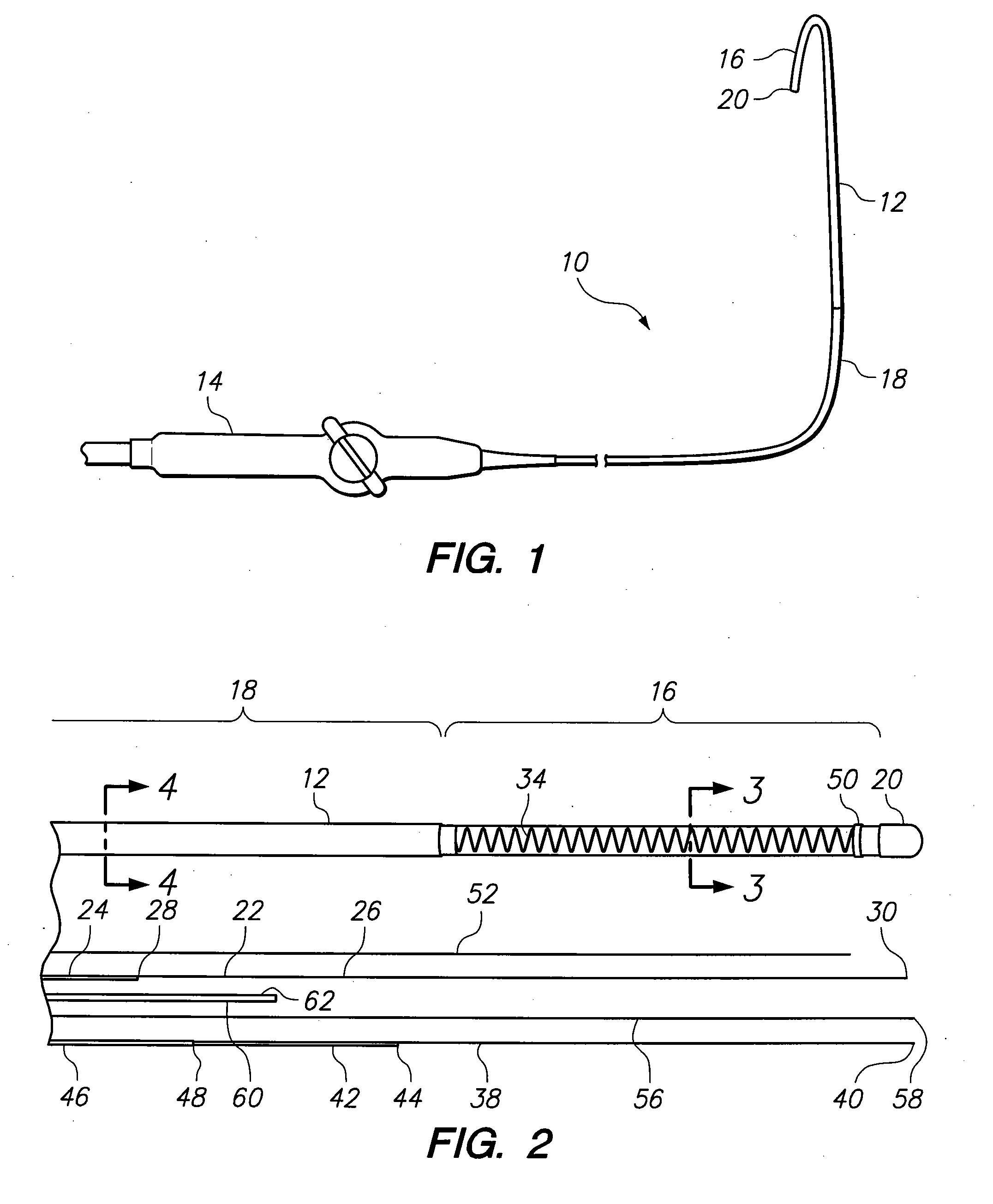
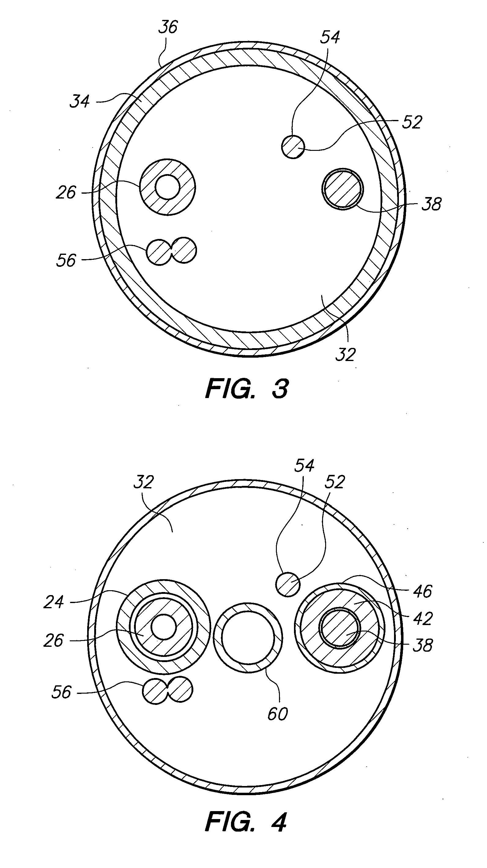
[0022]Referring initially to FIG. 1, a system (generally designated 10) having a cryo-catheter 12 and catheter handle 14 is shown. For the present invention, the system 10 can be used as part of a cryoablation apparatus to cryoablate a lesion in a body conduit of a patient (patient not shown). Although the system 10 is described herein for a catheter 12, those skilled in the pertinent art will appreciate that the systems and methods described herein can be implemented with other applicators such as a cryo-probe (not shown) that is configured to contact and ablate exposed tissue.

[0023]As indicated in FIG. 1, the cryo-catheter 12 includes an articulation segment 16 that can be deflected using the catheter handle 14 into different configurations and orientations. FIG. 1 further shows that the cryo-catheter 12 includes a braided segment 18 that extends distally from the catheter handle 14 to the articulation segment 16. It can be further seen that the cryo-catheter 12 includes a distal ...


PUM


Abstract

A configuration for a cryo-catheter which optimizes both the catheter's outer diameter and the size of the catheter's internal refrigerant flow path is described. Specifically, the inner dimensions of the cryo-catheter are configured to accommodate a pre-selected flow of refrigerant into the catheter's distal tip, and a return flow of refrigerant from the distal tip. The return flow is established in the void spaces between a refrigerant supply line and the inner wall of the catheter body. The available void space varies along the catheter length and depends on the presence/absence of various catheter accessories (i.e. pull wires, pressure tubes, etc.) which typically only extend through a portion of the catheter length. The disclosed configuration ensures that the cryo-catheter does not operate in a refrigerant limited condition, maintains the refrigerant as a liquid in the supply tube, and maintains the return line pressure at about 1 atmosphere.

Description

FIELD OF THE INVENTION[0001]The present invention pertains generally to systems and methods for cryoablating tissue. More particularly, the present invention pertains to a configuration for a cryo-catheter having an active articulation system. The present invention is particularly, but not exclusively, useful as a configuration for a cryo-catheter which optimizes both the catheter's outer diameter and the size of the catheter's internal refrigerant flow path.BACKGROUND OF THE INVENTION[0002]Cryoablation has been successfully used in various medical procedures to destroy or deactivate selected tissues. In this context, it has been determined that cryoablation procedures can be particularly effective for curing heart arrhythmias, such as atrial fibrillation. It is believed that at least one-third of all atrial fibrillations originate near the ostia of the pulmonary veins, and that the optimal treatment technique is to treat these focal areas through the creation of circumferential les...

Claims


Application Information

Patent Timeline
Patent Type & Authority Applications(United States)
IPC IPC(8): A61B18/02
CPCA61B18/02A61B2017/003A61B2018/0212A61B2018/0262
Inventor LENTZ, DAVID J.ALLEN, JILLIAN K.
Owner CRYOCOR
Why Eureka
Try Eureka