Air separation method and apparatus

a separation method and air technology, applied in lighting and heating equipment, solidification, refrigeration and liquid storage, etc., can solve the problems of increasing fabrication costs over the heat exchanger being contemplated, affecting the intended distillation, etc., and achieve the effect of less expensiv

Inactive Publication Date: 2008-12-18
PRAXAIR TECH INC
View PDF15 Cites 36 Cited by
  • Summary
  • Abstract
  • Description
  • Claims
  • Application Information

AI Technical Summary

Benefits of technology

[0023]A pump can be provided to pressurize a liquid oxygen stream composed of a liquid oxygen column bottoms of the lower pressure column. The pump is connected to the higher pressure heat exchanger so that the liquid oxygen stream after having been pumped is introduced into the higher pressure heat exchanger and vaporized. The higher pressure heat exchanger and the lower pressure heat exchanger are also in flow communication with the lower pressure column to receive first and second subsidiary waste nitrogen streams, respectively. The first and second subsidiary nitrogen streams are formed from a waste nitrogen stream removed from the lower pressure column, for thermal balance purposes. The higher pressure heat exchanger is configured such that a smaller cross-sectional flow area for the first subsidiary waste nitrogen stream exists within the higher pressure heat exchanger than would otherwise be required to produce a pressure drop in the first subsidiary waste nitrogen stream equal to that of the second subsidiary waste nitrogen stream in the lower pressure heat exchanger. Again, as outlined above, this allows the higher pressure heat exchanger to be fabricated in a less expensive manner.

Problems solved by technology

As indicated above, divergence of temperatures at the warm end of the lower pressure heat exchanger will produce warm end losses of refrigeration and such divergence in temperature at the cold end of the higher pressure heat exchanger will result in the liquid air evolving into an undesirable high vapor fraction upon its expansion that will upset the intended distillation to be carried out in the air separation unit.
If for example, the higher pressure heat exchanger were made of plate-fin construction and used a higher cross-sectional flow area for the first subsidiary waste nitrogen stream, thicker parting sheets and side bars would otherwise be required with the result in increased fabrication costs over the heat exchanger being contemplated by the present invention.

Method used


Image

  • Air separation method and apparatus
  • Air separation method and apparatus
  • Air separation method and apparatus

Examples


Embodiment Construction

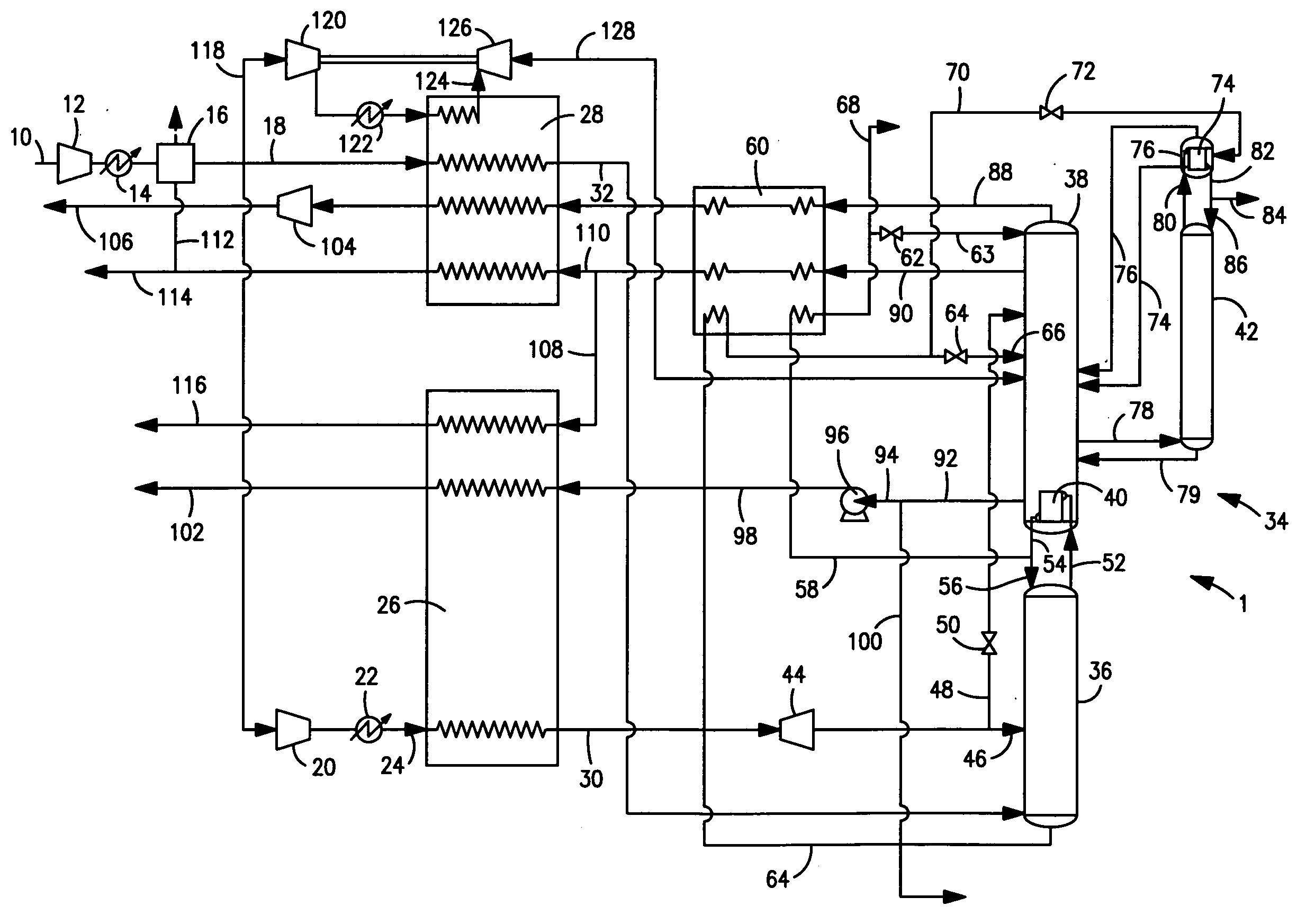
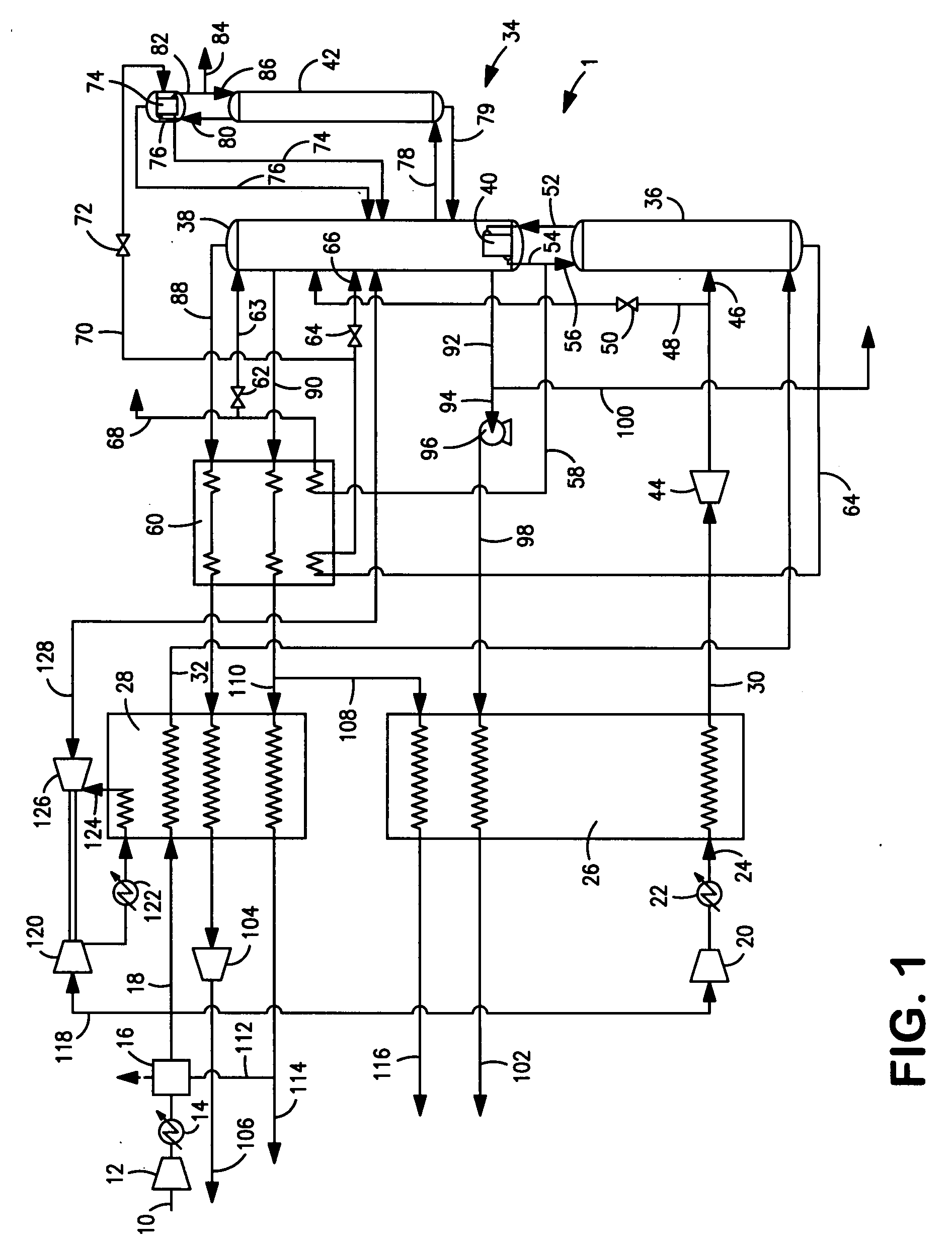
[0035]With reference to FIG. 1, an apparatus 1 in accordance with the present invention is illustrated.

[0036]An air stream 10 is compressed in a main air compressor 12. After removal of the heat of compression by a first after-cooler 14, air stream 10 is purified within a purification unit 16. Purification unit 16, as well known to those skilled in the art can contain beds of adsorbent, for example alumina or carbon molecular sieve-type adsorbent to adsorb the higher boiling impurities contained within the air and therefore air stream 10. For example such higher boiling impurities as well known would include water vapor and carbon dioxide that could tend to freeze and accumulate at the low rectification temperatures contemplated by apparatus 1. In addition, hydrocarbons can also be adsorbed that could collect within oxygen-rich liquids and thereby present a safety hazard. A first compressed and purified air stream 18 is produced from a first part of air stream 10 after having been c...


PUM


Abstract

A compressed air stream is cooled to a temperature suitable for its rectification within a lower pressure heat exchanger and a boosted pressure air stream is liquefied or converted to a dense phase fluid within a higher pressure heat exchanger in order to vaporize pumped liquid products. Thermal balancing within the plant is effectuated with the use of waste nitrogen streams that are introduced into the higher and lower pressure heat exchangers. The heat exchangers are configured such that the flow area for the subsidiary waste nitrogen stream within the higher pressure heat exchanger is less than that would otherwise be required so that the subsidiary waste nitrogen streams were subjected to equal pressure drops in the higher and lower pressure heat exchangers. This allows the higher pressure heat exchanger be fabricated with a reduced height and therefore a decrease in fabrication costs.

Description

FIELD OF THE INVENTION[0001]The present invention relates to a method and apparatus for separating air into nitrogen and oxygen-rich products by cryogenic distillation in which the air, after having been compressed and purified, is cooled to a temperature suitable for its distillation through indirect heat exchange with the nitrogen and oxygen-rich products within heat exchangers. More particularly, the present invention relates to such a method and apparatus in which a liquid oxygen stream is pumped and then vaporized in a separate heat exchanger through indirect heat exchange with part of the air that has been further compressed in a booster compressor.BACKGROUND OF THE INVENTION[0002]It is well known in the art to separate air into nitrogen and oxygen-rich products and also potentially an argon-rich product by cryogenic distillation. In accordance with such method, the air is compressed and purified and then cooled to a temperature suitable for its distillation within a heat exch...

Claims


Application Information

Patent Timeline
Patent Type & Authority Applications(United States)
IPC IPC(8): F25J3/04F25J3/00
CPCF25J3/04084F25J3/0409F25J3/04187F25J3/04218F25J3/04236F25J3/04303F25J3/04387F25J3/04412F25J3/04678F25J2240/10F25J2290/12F25J3/0423F25J5/00F25J2290/32F25J2290/44
Inventor PROSSER, NEIL MARKJIBB, RICHARD JOHN
Owner PRAXAIR TECH INC
Why Eureka
Try Eureka