Vehicle rollover test fixture

a test fixture and vehicle technology, applied in vehicle testing, structural/machine measurement, instruments, etc., can solve the problems of large infrastructure, unrepeatability of vehicle performance experiments, and inability to test vehicle performance, etc., to avoid damage and limit further damage to the test vehicle

Inactive Publication Date: 2008-12-18
SAFETY TESTING INT
View PDF9 Cites 11 Cited by
  • Summary
  • Abstract
  • Description
  • Claims
  • Application Information

AI Technical Summary

Benefits of technology

[0012]A test fixture for rollover crash testing of a test vehicle incorporates a cradle to support and rotate a test vehicle. The cradle is carried by a structure to position and releasably hold the cradle. A sled having a contact surface simulating a roadway is carried on a bearing assembly extending beneath the structure and the cradle fixture. The cradle, with the supported vehicle, is rotated at a predetermined rate to simulate the initial contact velocities for a rollover event and released from the structure responsive to a sensor for contact on a drop impact zone on the contact surface. The bearing supported sled reacts to the impacting vehicle and is displaced along the bearing assembly. The vertical motion of the cradle is arrested at the event completion to avoid damage to the bearing and sled system as well as limiting further damage to the test vehicle.

Problems solved by technology

Rollovers have been and continue to be a significant cause of occupant fatalities and serious injuries.
To date, the experiments to determine vehicle performance have been criticized as unrepeatable and, thus, inappropriate for vehicle or component design and testing and / or compliance type testing.
Various other test fixtures have been developed that addresses some of these issues, but require a large infrastructure to run and do not fully control the vehicle after the first impact and during the test (reference: U.S. Pat. No. 6,651,482).
Another device (reference U.S. Pat. No. 6,256,601) articulates about a pivot but does not provide a full rollover capability, nor does it provide a means to simulate a roll about the true roll axis of a vehicle.
In addition, none of the other test methods allow for the direct measurement of the loads applied to the vehicle, which are important to evaluating and understanding the dynamics of a rollover event.
The major drawback of these tests is the unrepeatable nature of the testing.
While these tests will allow insight into vehicle performance, they do not allow a study of vehicle and component performance during an impact that can be exactly repeated to determine changes in vehicle structure or geometry through repeated tests.
In particular, earlier test methods do not result in consistent impacts due to variations in tire to dolly or tire to road impacts before the roof structure interaction or are not controlled after the roof impacts.
These differences lead to several shortcomings in the previous methodology including the inability to measure the direct forces on the roof of the vehicle, the inability to control the vehicle after the desired roof contacts, the artificial positioning of anthropomorphic crash test dummies if included, the inability of the system to directly determine the roof crush from the desired impact, the inability to evaluate damage on a per roll and / or cumulative basis.
The fixture described also does not provide the means to rotate the test vehicle for the purposes to measure and evaluate vehicle structural integrity.
Prior art systems are not presently able to provide control of the vehicle in pitch and yaw at the initiation of and during test sequences.
While coupled motion of the sled and rotation of the vehicle prior to impact provide repeatable test results with highly accurate simulation, the structural and system requirements for creating and coordinating the moving sled contact zone are complex and costly.

Method used


Image

  • Vehicle rollover test fixture
  • Vehicle rollover test fixture
  • Vehicle rollover test fixture

Examples


first embodiment

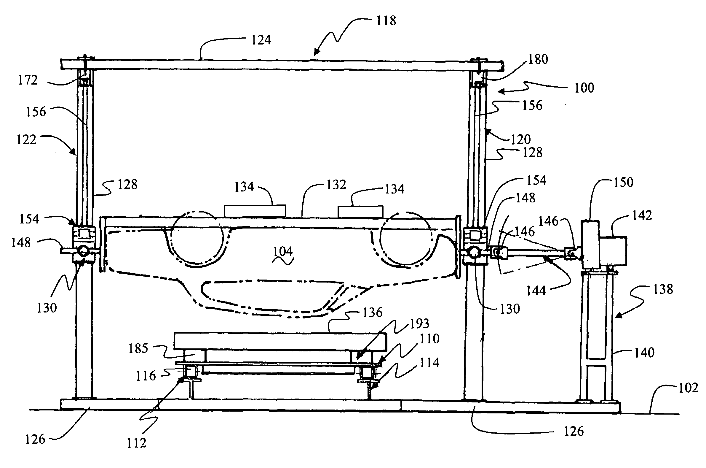
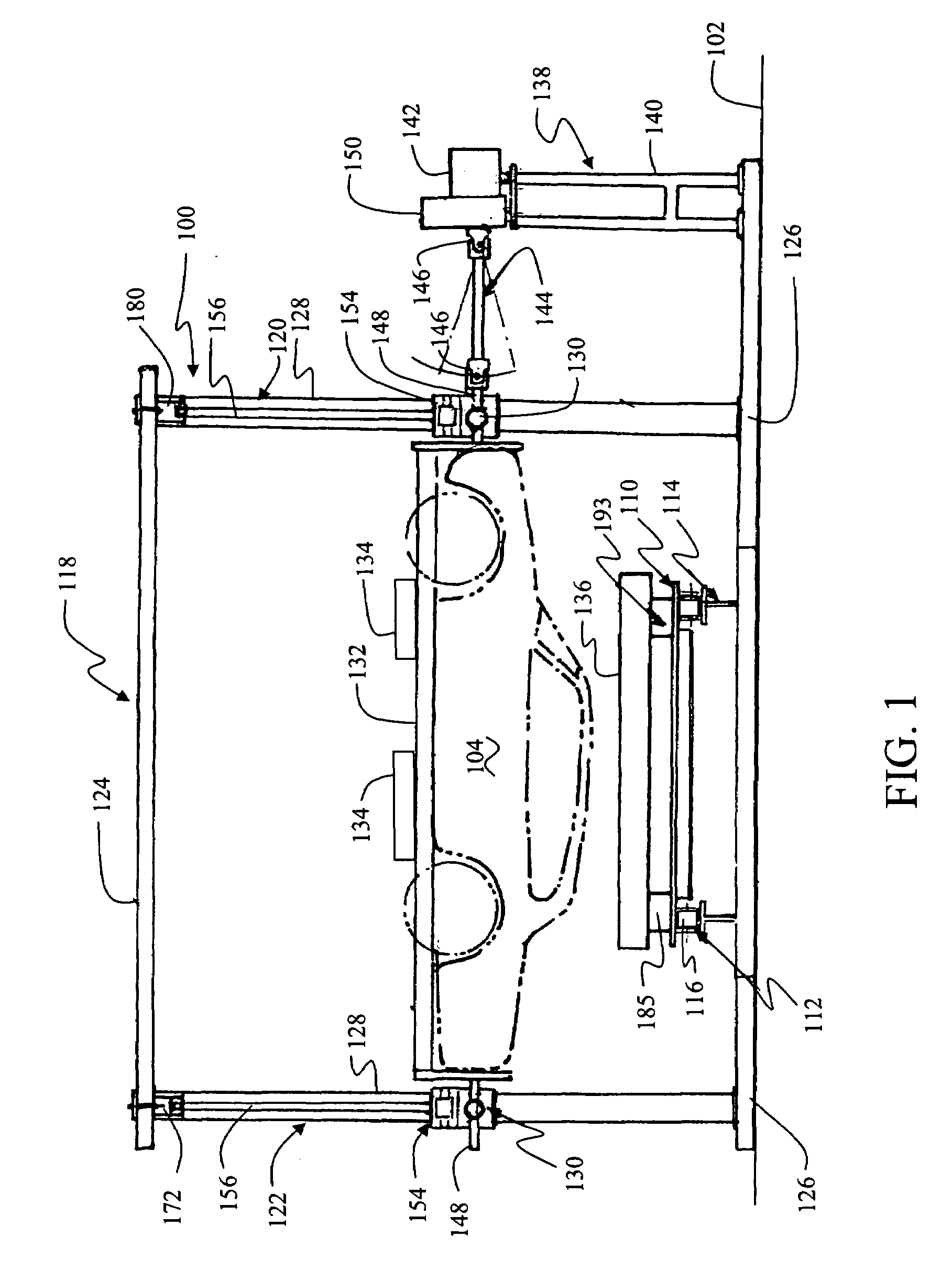
[0035]A detailed implementation of the structure of FIG. 5 is shown in FIGS. 6A-6C. Vehicle cradle 508 is suspended from suspension beam 506 with drop rods 514a and 514b which are attached to rotational support bosses 516a and 516b at opposite ends of the cradle. The cradle rotates between the support bosses for positioning of the vehicle and inducing the angular rotation of the vehicle for the appropriate test protocol as previously described. The drop rods extend through slip bearings in actuation assemblies 518a and 518b which function in a manner similar to guide bearings on the drop columns as described with respect to the The actuation assemblies additionally include a brake to capture the drop rods for vertical capture of the cradle and vehicle at the conclusion of the test to arrest further vertical motion as previously described.

[0036]Control beam 510 is carried by structural supports 520a and 520b which are in turn carried on horizontal beam elements 522a and 522b. For th...

second embodiment

[0039]FIGS. 7A-7C provide isometric, side and end views of the second embodiment with the pitch and yaw of the vehicle cradle modified from the orthogonal settings. In the views shown, the cradle is pitched tail down (as opposed to nose down as shown in FIG. 5) by extending the telescoping adjusting elements 526c and 526d to raise support beam 504b and lowering the telescoping adjusting elements 526a and 526b to lower support beam 504a. This support arrangement places suspension beam 506 at a first pitch angle relative to the plane of the sled for impact. Similarly, a yaw angle induced by sliding the ends of suspension beam 506 in opposite directions; forward along support beam 504a and rearward along support beam 504b. This places the cradle in a yawed position with respect to the directional axis of the sled. The control beam is similarly yawed by moving supports 520a and 520b along second horizontal support beams 522a and 522b. The angle of the control beam positions control arms...


PUM

PropertyMeasurementUnit
pitch angleaaaaaaaaaa
yaw angleaaaaaaaaaa
roll angleaaaaaaaaaa

Abstract

A test fixture for rollover crash testing of a test vehicle onto a moving surface employs a cradle to support and rotate the test vehicle. A vertical support structure to position and releasably holds the cradle. A moving sled having a contact surface and is carried by a guide extending beneath the structure and the cradle fixture. The cradle is rotated and released from the structure responsive to a sensor for contact within a drop impact zone on the contact surface of the moving sled. Vertical motion of the cradle is then arrested to prevent further damage to the test vehicle or the test structure.

Description

REFERENCE TO RELATED APPLICATIONS[0001]This application claims priority of U.S. Provisional Application Ser. No. 60 / 943,355 filed on Jun. 12, 2007 having the same title as the present application and copending with U.S. patent application Ser. No. 11 / 380,862 filed on Apr. 28, 2006 now U.S. Pat. No. 7,373,801 having the same title as the present application and common inventors.BACKGROUND[0002]1. Field of Invention[0003]This invention relates to an automotive vehicle test fixture. In particular, the invention relates specifically to a fixture to conduct dynamic, repeatable, controlled destructive rollover impact tests of both full scale vehicles and representations to evaluate strength and occupant protection characteristics of the vehicle roof and other vehicle components. The invention provides precise control of initial test parameters including drop height, contact roll rate, contact roll angle, pitch angle, yaw angle, post contact freefall height, vehicle moment of inertia, road...

Claims


Application Information

Patent Timeline
Patent Type & Authority Applications(United States)
IPC IPC(8): G01N3/00
CPCG01M17/0074
Inventor FRIEDMAN, DONALDJORDAN, ACEN
Owner SAFETY TESTING INT
Why Eureka
Try Eureka