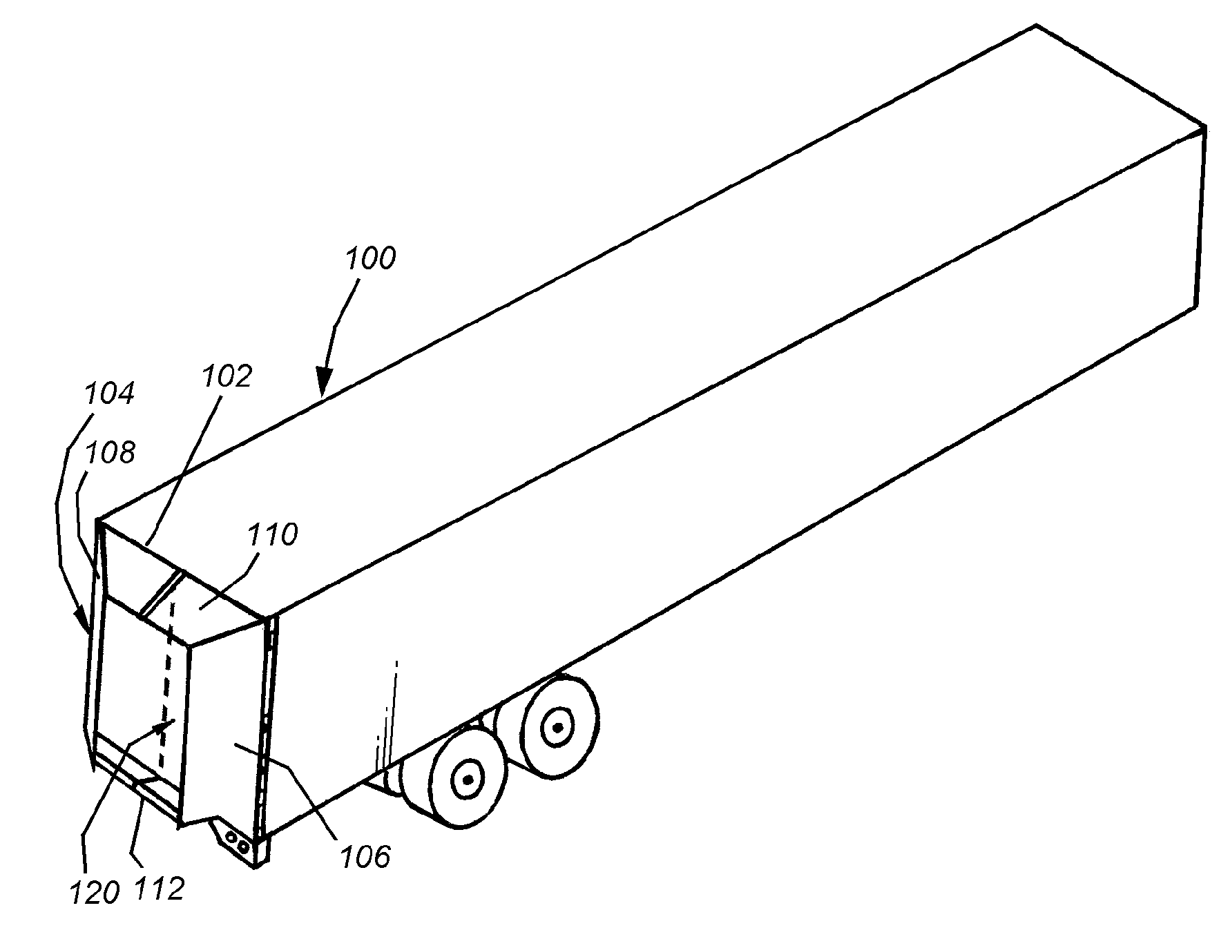
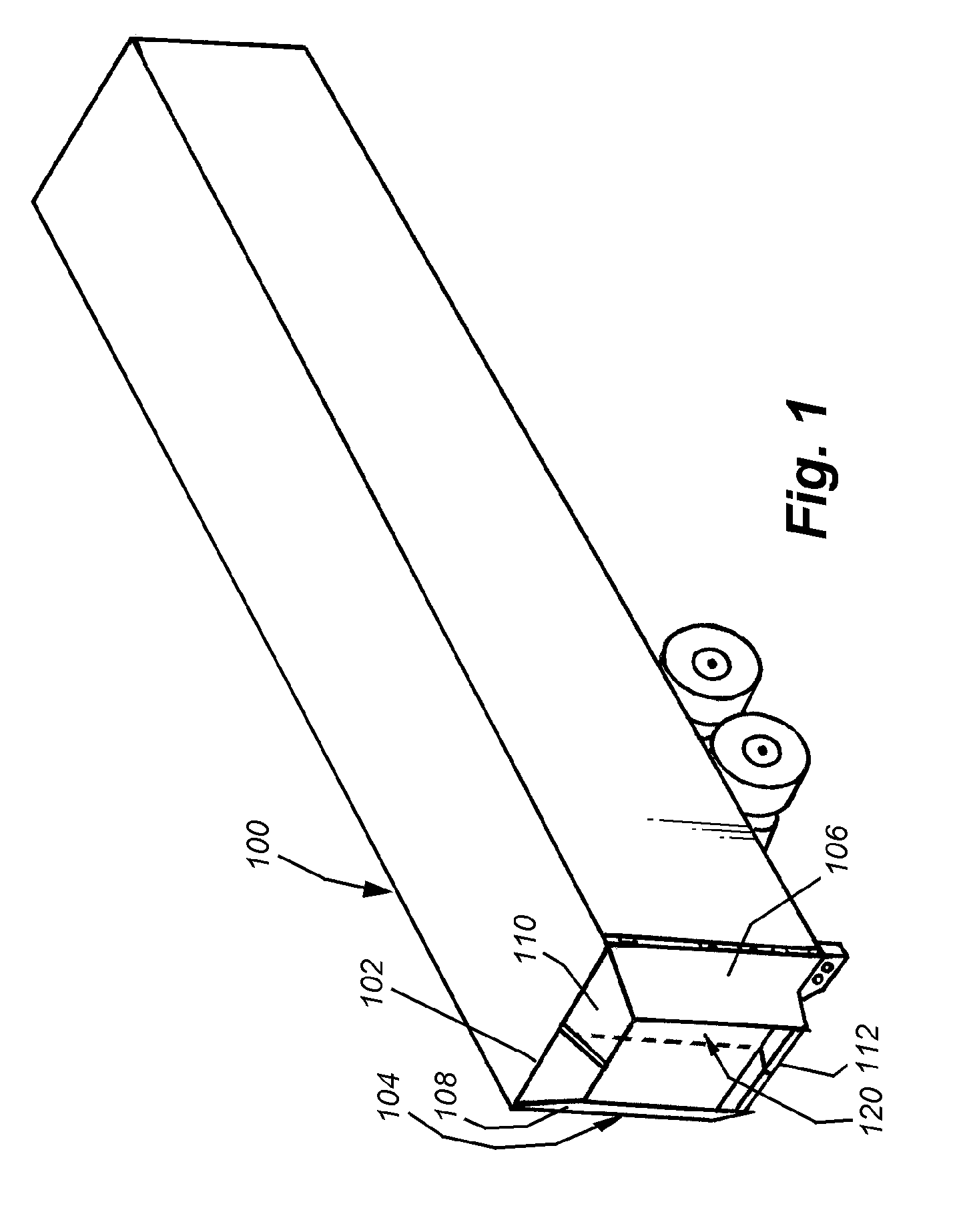
[0010]This invention overcomes the disadvantages of the prior art by providing an aerodynamic structure attached to the rear face of a truck cargo body, which rear typically contains a door
assembly, with a plurality of doors that swing open on hinges, or a single, full-width door, which rolls upwardly. The various embodiments of the invention allow an aerodynamic structure to be permanently attached to the rear of the trailer in a manner that would obscure access to the door(s) in a deployed position, in which the aerodynamic structure generates reduced drag on the trailer body, yet enables ready access to the door(s) in a folded position. The folded position still allows the rear of the trailer to be fully accessible for loading and unloading, and in the case of swinging, hinged doors (among others), allows the doors to be folded through a full 270-degree arc from a closed position to a position flush along the sides of the vehicle, with a minimal sideways projection. The various embodiments also enable relatively rapid and easy transition between the folded position and the deployed position using a variety of actuators and linkages that tie the folding and deployment of various panels of the structure together. This allows an operator to selectively fold and deploy the structure without undue effort or strength.
[0012]In another embodiment of this invention, all the panels of the aerodynamic structure portion on a given door are interconnected by hinges so that the overall tapered box defines an “origami” type of folding arrangement. In such an arrangement, a vertical, medial panel is divided into three separate panel sections with the its upper and lower panel sections joined to adjacent horizontal top and bottom surfaces. The horizontal upper and lower surfaces are, likewise, each divided diagonally into a pair of upper and lower panel sections, respectively. The opposing upper and lower panels are hingedly attached to a one-piece outer vertical panel. When either the medial panel or the outer panel is moved toward or away from the underlying truck rear face / door, the force is transmitted throughout the structure, causing it to either fold or unfold, respectively. The separate panels are joined by sliding hinges or another type of hinge
assembly (such as a flexible material) that facilitates the folding of each panel over the other by allowing the joined panel to translate, as well as rotate in
two degrees of freedom. This facilitates the requisite origami folding pattern by allowing movement in
two degrees of freedom. This accommodates the fact that the panels have a finite thickness.
[0016]In illustrative embodiments of the present invention, the aerodynamic structure can be mounted on a door with extended hinges that either overlie conventional, original butt hinges of a retrofitted trailer door frame, or are placed remote from the original hinges. In an illustrative implementation, the hinges can be formed with a streamlined outer cover, or constructed as part of an overall, elongated butt plate with cutouts and clevis plates attached at desired locations based upon the locations of preexisting hinge clevises. The butt plate is applied to the corner of the trailer frame thereby forming a relatively continuous and streamlined rear hinge extension. The pivot axis points of the extended hinges allow for a larger swing that enable the thickened door with the folded stack-up of aerodynamic panels to open approximately 270 degrees to a position flush with the side of the trailer. This facilitates movement of the trailer into a narrow loading dock space without interference by the aerodynamic structure. The extended hinges of various embodiments can have pivot points located anywhere within an arc relative to the original hinge axis points so as to extend the swing of the door and allow the doors with folded panels to be located adjacent to the side of the trailer.
[0017]In another embodiment, instead of the above-described
single axis extended hinge, the extended hinge assembly can define a multi-axis hinge having at least one central hinge clevis. This multi-axis hinge assembly provides at least two separate, parallel hinge pivots that allow the thickened door unit (with attached spacer frame and nested, folded panels) to be opened a full 270 degrees so as to lie against the adjacent side of the cargo box. In one example, at least two of the hinge assemblies on each door can be geared so as to prevent
racking of the door as it swings by maintaining it within a predetermined swing pattern as defined by meshing gears in each assembly. In other examples, the doors can be conventionally hinged, using extended hinge pivots, or another type of multi-axis hinge, such as a four-bar linkage, can be employed.
[0018]In various embodiments in which the trailer employs hinged doors, lock rods are used to secure the doors near the medial
joint line therebetween. To allow for clearance over these lock rods when the panel structure is folded, the panels (upper and lower, for example) can be located on hinges that define an axis with a rearwardly directed angle when folded against the door so as to provide the needed clearance. This angled fold-line allows for decreased overall stack-up at the lateral side of the door, which results in less room needed between trailers at a dock when the doors are open. The panels can be mounted to the door on hinges with pivot points remote from the inner surface of the respective panel so that the forward (trailer-frame-confronting) edge is located adjacent to the side of the trailer body / door frame for added streamlining.
[0020]The upper and lower panels of the structure can account for variability in the width of the doors, and any resulting gap by providing a medial wiper that seals between the medial facing edges of the panels to reduce / eliminate air leakage into the cavity defined by the panels. Other seals between panels, and between the panels and the door frame can also be provided. The presence of seals and other structures between the door and the frame can be accommodated by a spacer that positions the panel hinges rearwardly to overlie, for example, a preexisting door-to-frame
gasket. The size of the spacer can be to allow
accommodation of different-sized gaskets and differing positions for the forward end of the panel (to align its confrontation with the door frame edge).

