In-vehicle mount electronic controller

a technology of electronic controller and in-vehicle mount, which is applied in the direction of process and machine control, instruments, safety/protection circuits, etc., can solve the problems of not aiming to accurately check the output voltage precision and thus predict the occurrence of abnormalities, and needing complicated processing, etc., to achieve accurate detection of the presence or absence of abnormalities

Active Publication Date: 2008-12-18
MITSUBISHI ELECTRIC CORP
View PDF8 Cites 58 Cited by
  • Summary
  • Abstract
  • Description
  • Claims
  • Application Information

AI Technical Summary

Benefits of technology

[0007]An object of the present invention is to provide an in-vehicle mount electronic controller that can accurately detect the presence or absence of abnormality with ...

Problems solved by technology

Provision of many output voltages induces a problem that complicated processing is needed when some output voltage is abnormal.
However, there is not presented a concept associated with the detection of abnormality of each output voltage.
Furthermore, the constant-voltage power supply source shown in JP2001-352675A aims to prevent burnout of the constant-voltage controlling transistor due to abnormality of ove...

Method used


Image

  • In-vehicle mount electronic controller
  • In-vehicle mount electronic controller
  • In-vehicle mount electronic controller

Examples


first embodiment

(1) Detailed Description of Construction

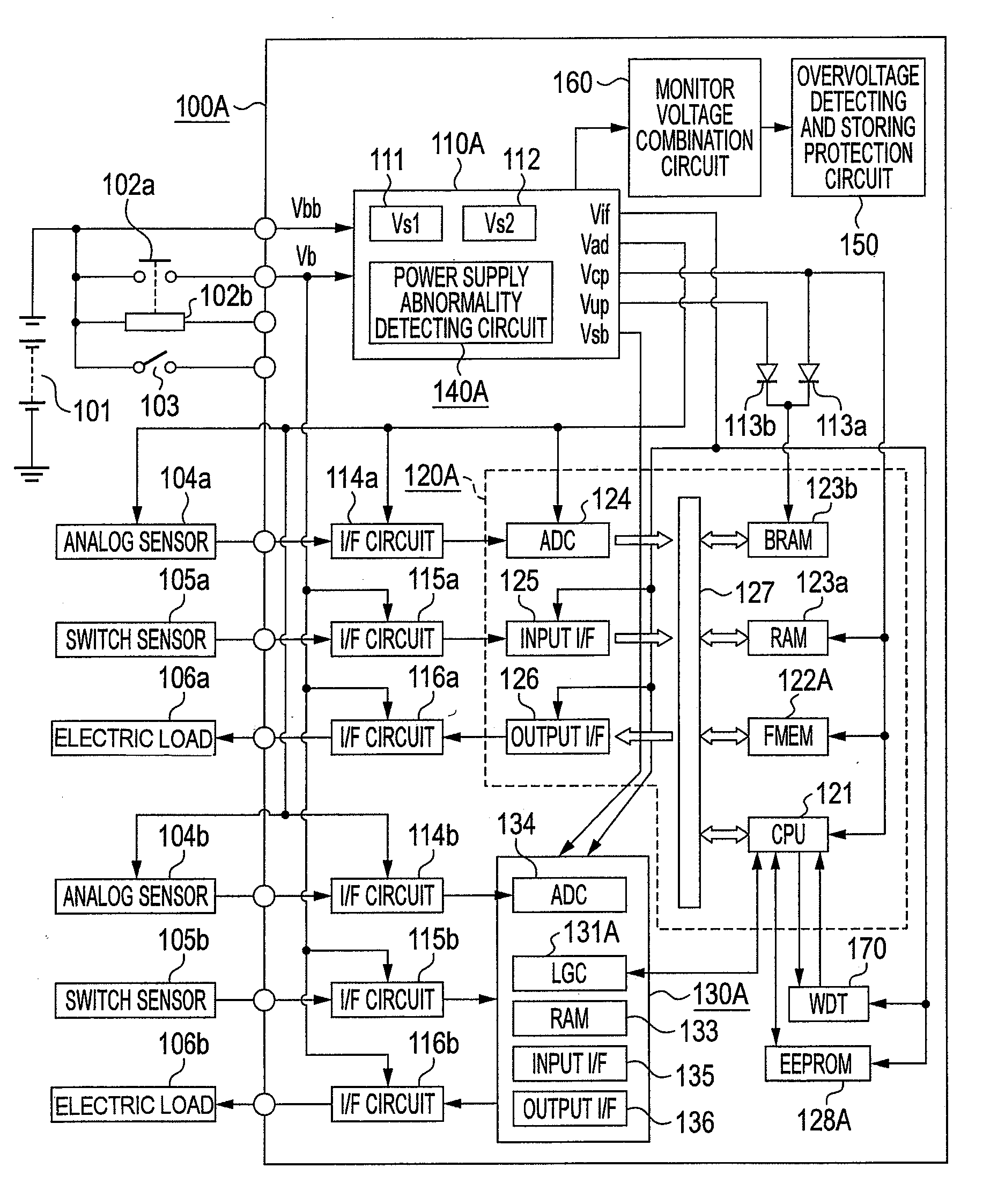
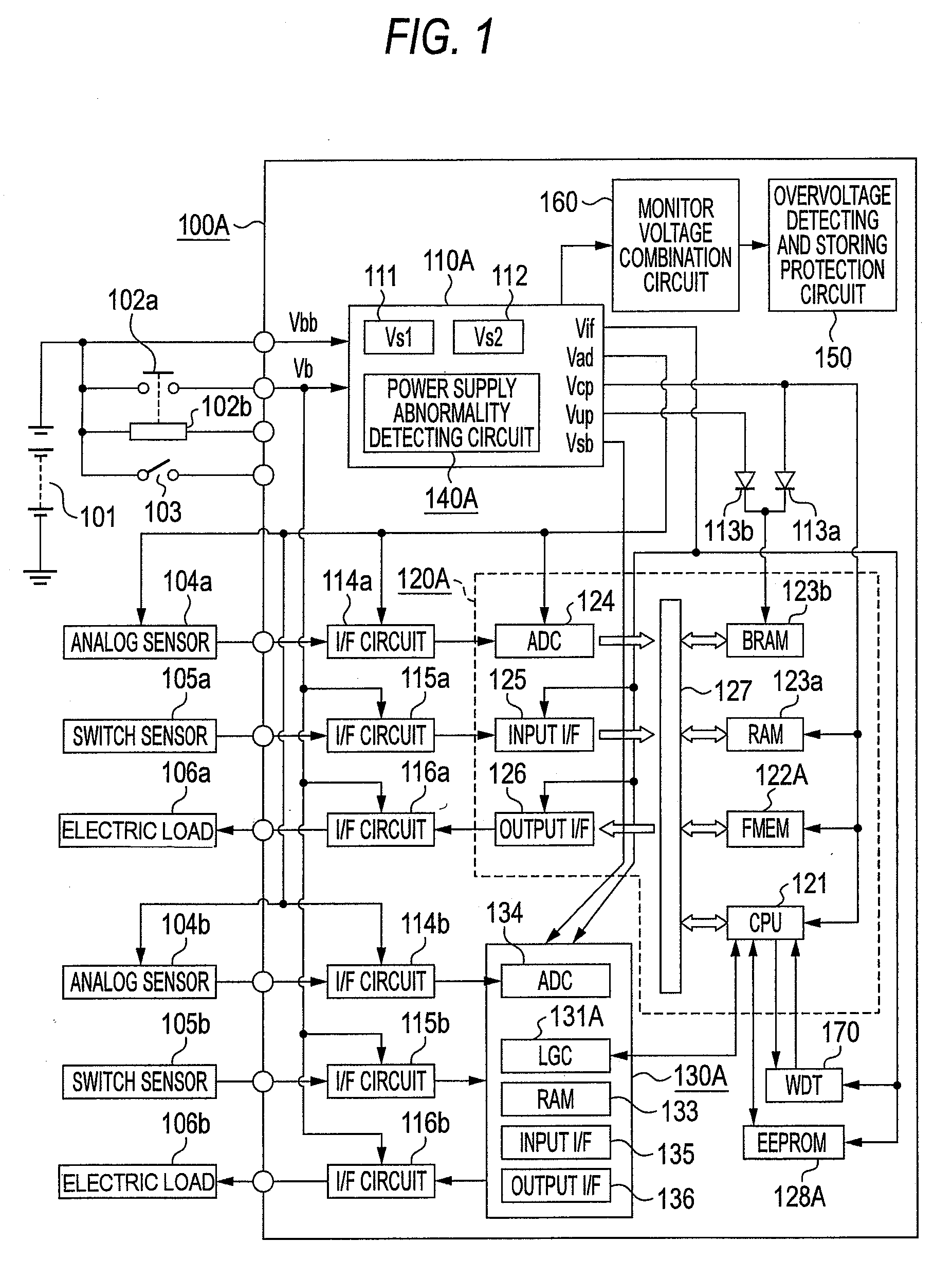
[0042]FIG. 1 is an overall circuit diagram showing a first embodiment of an in-vehicle mount electronic controller according to the present invention. First, the construction of an in-vehicle mount electronic controller 100A according to a first embodiment will be described in detail with reference to FIG. 1. In FIG. 1, a main power supply voltage Vb is supplied from an in-vehicle mount battery 101 through an output contact point 102a of a power supply relay to the in-vehicle mount electronic controller 100A, and an auxiliary power supply voltage Vbb is directly supplied from the in-vehicle battery 101 to the in-vehicle mount electronic controller 100A even when the output contact point 102a opens the circuit. An exciting coil 102b of the power supply relay is energized when a power supply switch 103 closes the circuit, whereby the output contact point 102a closes the circuit. When the power supply switch 103 is controlled to open the circuit,...

second embodiment

(1) Detailed Description of Construction

[0154]FIG. 5 is an overall circuit diagram showing a second embodiment of the in-vehicle mount electronic controller according to the present invention. The construction of the second embodiment will be described in detail by concentrating on the difference from the first embodiment of FIG. 1 with reference to FIG. 5. In FIG. 5, the same reference numerals as FIG. 1 represent the same or corresponding parts.

[0155]In FIG. 5, a constant-voltage power supply source 110B in the in-vehicle mount electronic controller 100B of the second embodiment is characterized in that the output voltage Vif of the second constant-voltage power supply circuit 20 is used as an input voltage to the third constant-voltage power supply circuit 30 in place of the main power supply voltage Vb as described later with reference to FIG. 6, and thus the power consumption of the third constant-voltage power supply circuit 30 can be greatly suppressed. However, the power con...

third embodiment

(1) Detailed Description of Construction

[0257]FIG. 9 is an overall circuit diagram showing a third embodiment of the in-vehicle amount electronic control according to the present invention. Referring to FIG. 9, the construction of the third embodiment will be described in detail by concentrically the difference point from that of FIG. 5. In FIG. 9, the same reference numerals as FIG. 5 represent the same or corresponding parts.

[0258]In FIG. 9, an in-vehicle mount electronic controller 100C of the third embodiment contains a constant-voltage power supply source 110C. The constant-voltage power supply source 110C generates fourth and fifth output voltages Vup and Vsb achieved by dropping the auxiliary power supply voltage Vbb as described later with reference to FIG. 10. A flash memory is used as the non-volatile program memory 122C contained in an integrated circuit element 120C, and a partial area thereof is used as the non-volatile data memory area 128C. A combination control circu...


PUM


Abstract

In an in-vehicle mount electronic controller, a constant-voltage power supply generates a high-precision small-capacity 5V output voltage Vad, a low-precision large-capacity 5V output voltage Vif and a low-precision large-capacity 3.3V output voltage Vcp, and also generates at least one of a low-precision small-capacity 2.8V output voltage Vup and a high-precision small-capacity 3.3V output voltage Vsb. A judgment signal input circuit logically combines comparison results of divided voltages of the above output voltages Vif, Vcp, Vup and Vsb with a divided voltage of the output voltage Vad as a reference voltage, and inputs relative voltage information ER2, ER3, ER4 and ER5 to a microprocessor. The microprocessor comprehensively judges the output voltages containing the comparison reference voltage, and reports abnormality or saves abnormality occurrence information.

Description

BACKGROUND OF THE INVENTION[0001]1. Field of the Invention[0002]The present invention relates to an in-vehicle mount electronic controller, and particularly to an in-vehicle mount electronic controller that contains a constant-voltage power supply source for generating plural stabilized output voltages and is improved so as to comprehensively detect the presence or absence of abnormality of each output voltage and a comparison reference voltage.[0003]2. Description of the Related Art[0004]A constant voltage source in an in-vehicle mount electronic controller is required to generate plural stabilized output voltages. For example, a constant-voltage power supply source disclosed in JP11-265225A titled as “POWER SUPPLY DEVICE FOR ENGINE CONTROLLER” generates various output voltages, 7.8V for a converter for flash writing, 5V for a high-precision sensor and a converter for ADC (analog / digital conversion), 3.3V for a converter for CPU, 3.3V for a converter for CPU standby, and 5V for a c...

Claims


Application Information

Patent Timeline
IPC IPC(8): H02M3/156H02H3/04
CPCB60R16/02H02J7/0029H02J2001/008H02M2001/009H02J1/082H02M1/009H02J7/00308
Inventor HASHIMOTO, KOJIIWAGAMI, YUKIYAMASHITA, MANABU
Owner MITSUBISHI ELECTRIC CORP
Why Eureka
Try Eureka