Automatic Gear Control Device

Inactive Publication Date: 2008-12-18
TOYOTA JIDOSHA KK
View PDF4 Cites 1 Cited by
  • Summary
  • Abstract
  • Description
  • Claims
  • Application Information

AI Technical Summary

Benefits of technology

[0013]Further preferably, the motive power source includes an engine, and the torque down control unit reduces an opening degree of a throttle valve adjusting an amount of air aspired into th

Problems solved by technology

Assuming that the accelerator pedal is depressed by the driver, if recovery from the engine torque down control is attained immediately when the turbine rotational speed appro

Method used


Image

  • Automatic Gear Control Device
  • Automatic Gear Control Device
  • Automatic Gear Control Device

Examples


Embodiment Construction

[0024]An embodiment of the present invention will be described hereinafter with reference to the drawings. In the following description, the same elements have the same reference characters allotted. Their designation and function are also identical. Therefore, detailed description thereof will not be repeated.

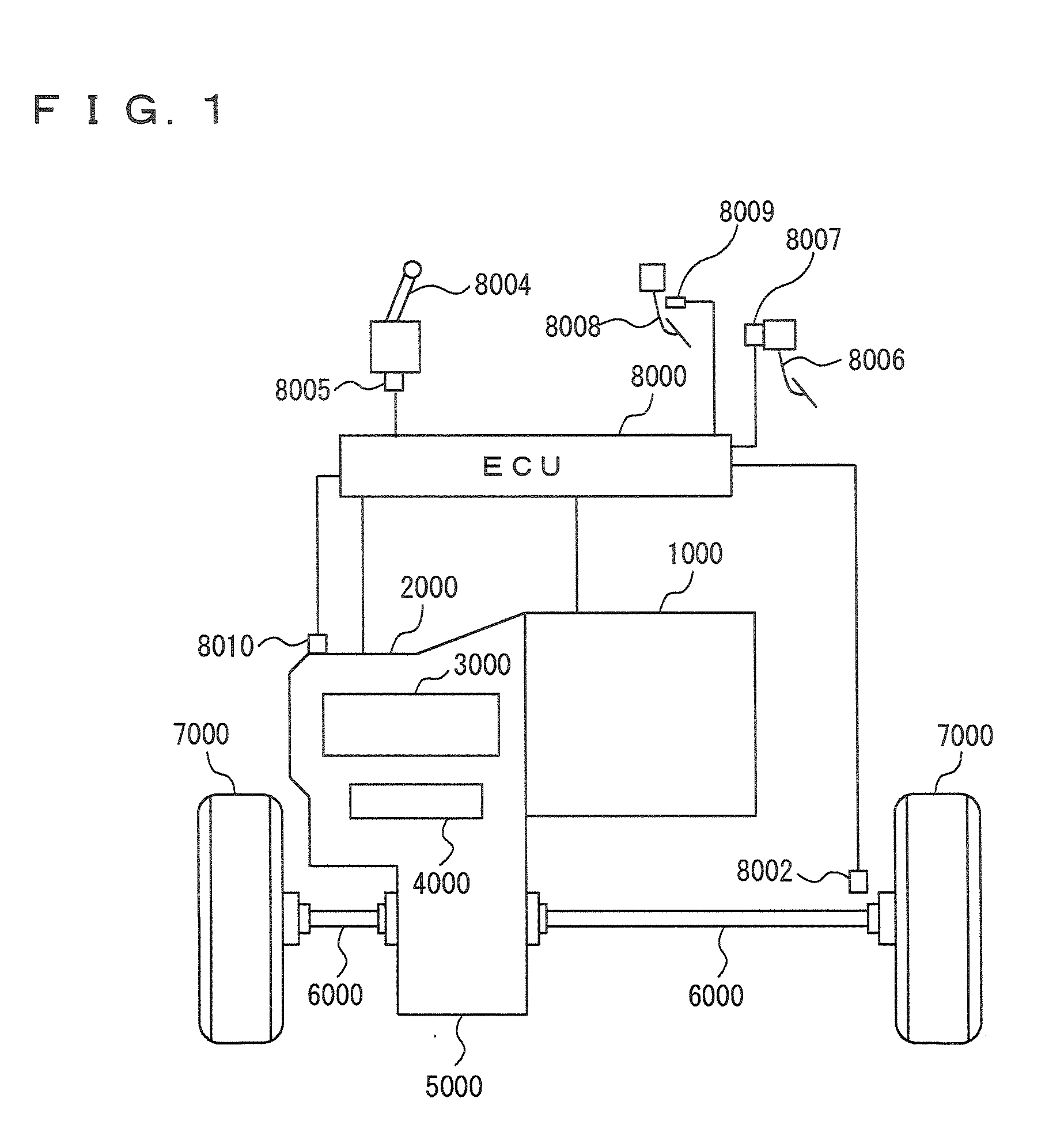
[0025]With reference to FIG. 1, a vehicle incorporating a control apparatus for an automatic transmission according to an embodiment of the present invention will be described. The vehicle is an FF (Front engine Front drive) vehicle. The vehicle incorporating the control apparatus for an automatic transmission according to the present embodiment is not limited to the FF vehicle.

[0026]The vehicle includes an engine 1000, a transmission 2000, a planetary gear unit 3000 constituting a portion of transmission 2000, an oil hydraulic circuit 4000 constituting a portion of transmission 2000, a differential gear 5000, a drive shaft 6000, a front wheel 7000, and an ECU 8000.

[0027]Engin...


PUM


Abstract

A control apparatus for an automatic transmission including a gear-type transmission mechanism connected to an output shaft of a motive power source, the gear-type transmission including plural frictional engagement elements. The control apparatus senses a power-on downshift in which the frictional engagement elements are engaged during a downshift in a driving state of the motive power source, controls the motive power source so that in the power-on downshift an output of the motive power source is reduced, counts a time during which an input rotational speed of the transmission mechanism approximates an after-shift synchronous rotational speed, and controls the motive power source so that, if the time exceeds a predetermined time while the output of the motive power source is reduced, recovery from the reduction of the output of the motive power source is attained.

Description

TECHNICAL FIELD[0001]The present invention relates to a control apparatus for an automatic transmission. In particular, the present invention relates to a control apparatus that can reduce a shift shock or the like during a downshift to realize excellent shift characteristics.BACKGROUND ART[0002]In order to suppress a sharp change in output shaft torque during a shift, that is, a shift shock, input torque to an automatic transmission is temporarily reduced. That is, an engine is controlled so that engine torque is reduced immediately before the end of an inertia phase during a downshift. If the input torque at a time point of synchronizing to a gear after the shift is great, then the change in the output shaft torque also becomes great. This disadvantageously increases the shift shock. Further, if torque on a frictional engagement apparatus that is engaged to perform the shift is small, the engagement timing thereof is disadvantageously delayed. Accordingly, in order to solve such p...

Claims


Application Information

Patent Timeline
IPC IPC(8): B60W10/10F02D29/00F02D41/04F02D45/00F16H59/18F16H59/42F16H61/04F16H61/68F16H61/684F16H61/686F16H63/50
CPCB60W10/06B60W10/11B60W30/19F02D23/00F02D29/02Y10T477/677F16H61/0437F16H63/502F16H2059/385F16H2306/42Y10T477/692F02D41/023
Inventor TOI, HIROOMIHATTORI, KOJISAGAWA, AYUMUOSHIMA, KOJIKIMURA, HIROMICHI
Owner TOYOTA JIDOSHA KK
Why Eureka
Try Eureka