
Density filter, method of forming the density filter and apparatus thereof

a density filter and filter body technology, applied in the field of density filters, can solve the problems of deterioration of picture quality owing to image defocusing, insufficient reflection prevention effect, and extremely inferior yield

Inactive Publication Date: 2008-12-25
NISCA KK
View PDF3 Cites 63 Cited by
  • Summary
  • Abstract
  • Description
  • Claims
  • Application Information

AI Technical Summary

Benefits of technology

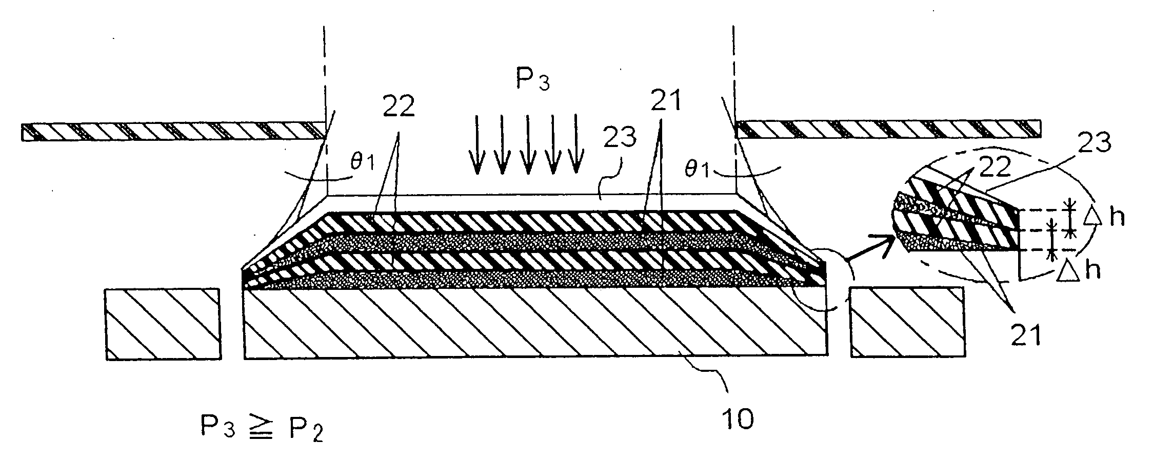
[0020]At the outset, the density filter is composed of a substrate, dielectric substance layers and metal film layers formed in lamination on the substrate. The dielectric substance layers are coated by sputtering targets of dielectric substances with an introduction gas, followed by applying a reactive gas. The metal film layers are coated by sputtering the targets of metal substances with the introduction gas, and when sputtering the targets, the dielectric substance layers and the metal film layers have gradation range layers with the thicknesses decreasing by diffusion of sputtering particles from the mask opening edge of mask plate forming film coating gap in relation with the substrate.
[0021]Further, in the film coating method of forming of the density filter according to an embodiment of the present invention, for forming the dielectric substance layers and the metal film layers in lamination on a substrate by sputtering a plurality of targets composed of at least first and second substances different in the optical characteristic, the dielectric substance layers are coated with sputter particles on the film coating by sputtering the targets with the introduction gas, followed by applying plasma to the film, and the metal film layers are performed with sputtering to the targets of metal substances with the introduction gas and coated, on the substrate, with films with the sputter particles or compounds of the sputter particles and the reactive gas. The dielectric substance film layers and the metal film layers are coated by (1) attaching the substrate onto a cylindrical rotation drum disposed within the film coating chamber, (2) placing the targets substantially in parallel to the surfaces of the substrates with plate mater

Problems solved by technology

Recently, with the advancement of high resolution imaging cameras, if closing quantity of light under a condition of bright subjects to be imaged, deteriorations in picture quality owing to image defocusing occur.
Such film structures attenuate light to adjust transmitted light quantity, but if density gradient of the dielectric film is large, there is a problem in that a reflection preventing effect cannot be enough obtained.
But, the above-mentioned method has a disadvantage in that, when producing plural sheets of filter blank materials at the same time, a film thickness is different per each of individual blank materials so that yields are extremely inferior.
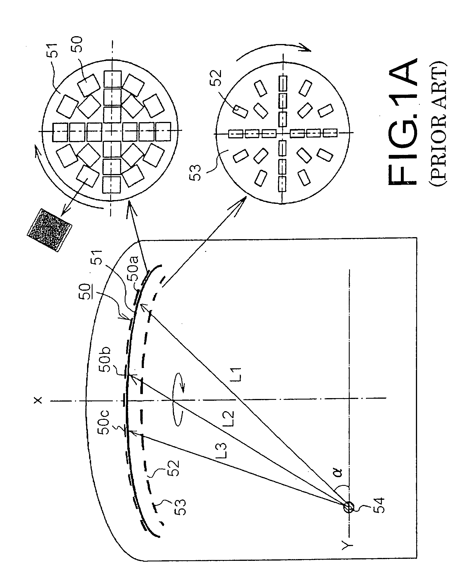
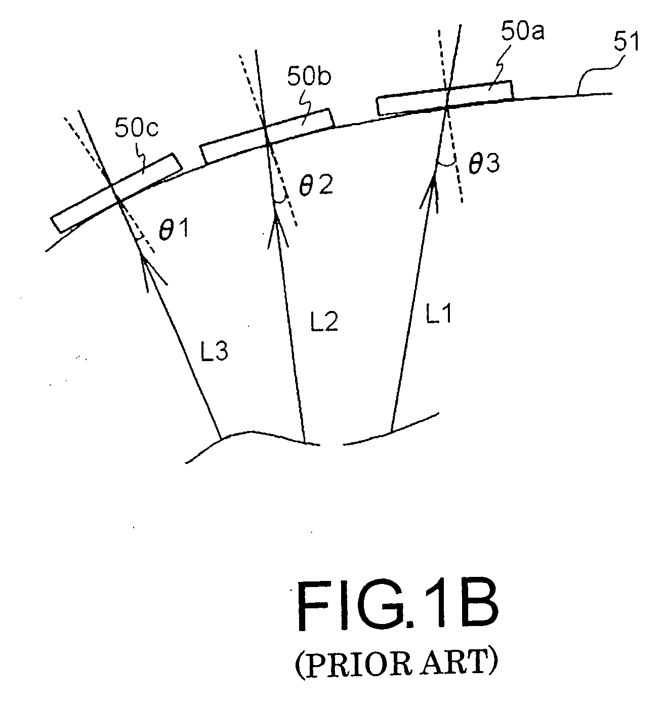
In the film coating method of the gradation filter by the prior evaporation equipment, the involved problems have been known that when producing plural substrates at the same time, a large distribution occurs in each of the optical characteristics, and the layers in the gradation range do not linearly attenuate.
This change makes the thicknesses of the coated film unstable, and the film thickness as geometrically formed cannot be obtained.
Since such oxide shift occurs at random by the film coating means, this is considered to be a cause of not forming a stable film layer.

Method used


Image

  • Density filter, method of forming the density filter and apparatus thereof
  • Density filter, method of forming the density filter and apparatus thereof
  • Density filter, method of forming the density filter and apparatus thereof

Examples


Embodiment Construction

[0045]The invention will be explained based on preferred embodiments shown in the drawings. FIGS. 3A and 3B show schematic views of causing the evaporation components to fly from the target, and FIGS. 4A and 4B show the arranging relation of the substrate and the target attached to the rotation drum, and those are the model views showing the conceptual constitution concerned with the embodiments of the present invention.

[0046]The film coating method of the density filter will be explained. With respect to the light reducing filter or density filter 43, as shown in FIGS. 5F and 5H, the light reducing layer or density film 20 of light absorption property is formed on the substrate or substrate 10. The density film 20 is formed in an isoconcentration or equal concentration range 20a having uniform thicknesses and uniform transmittance and a gradation range 20b of decreasing film thicknesses. The density filter 43 is structured in lamination with the metal film layers 21 rich in light a...


PUM

PropertyMeasurementUnit
Thicknessaaaaaaaaaa
Pressureaaaaaaaaaa
Densityaaaaaaaaaa

Abstract

A film coating method enables, when forming film layers in response to optical characteristics on a substrate, to coat gradation range layers of decreasing thickness without distributions, and to coat films on a plurality of substrates at the same time. The gradation range layer is formed by sputtering evaporation targets of dielectric substances with an introduction gas, followed by forming the films with compounds generated by applying a reactive gas to the films.

Description

BACKGROUND OF THE INVENTION AND RELATED ART STATEMENT[0001]The present invention relate to a density filter for adjusting quantity of light of an imaging camera, a method for forming the density filter and an apparatus for forming the same. In particular, the invention relates to a gradation film coating method and a film coating apparatus or equipment where a density characteristic of the density filter continuously decreases.[0002]In general, the density filter has broadly been used in IRIS. The density filter is form by a thin film, that has a superior light absorption characteristic, on a resin substrate. The density filter is known in coating thin films having uniform mono-density, in dividing film coatings into several ranges of different densities, and in coating thin films with gradation of density distribution which continuously changes.[0003]Recently, with the advancement of high resolution imaging cameras, if closing quantity of light under a condition of bright subjects ...

Claims


Application Information

Patent Timeline
IPC IPC(8): G02B5/22B32B37/06C23C14/34
CPCB32B37/24B32B38/0008B32B2037/243B32B2559/00C23C14/044C23C14/34C23C14/3464G02B5/205C23C14/048
Inventor NAKAJIMA, KATSURAKOHYA, SHOICHI
Owner NISCA KK
Learn More