
Low Power Radio Device With Reduced Interference

a radio device and low power technology, applied in multiplex communication, polarisation/directional diversity, high-level techniques, etc., can solve problems such as interference to mobile terminals, uwb devices may cause interference at 4g mobile terminals, etc., and achieve the effect of amplitude of radio signals

Inactive Publication Date: 2008-12-25
NOKIA CORP
View PDF0 Cites 16 Cited by
  • Summary
  • Abstract
  • Description
  • Claims
  • Application Information

AI Technical Summary

Benefits of technology

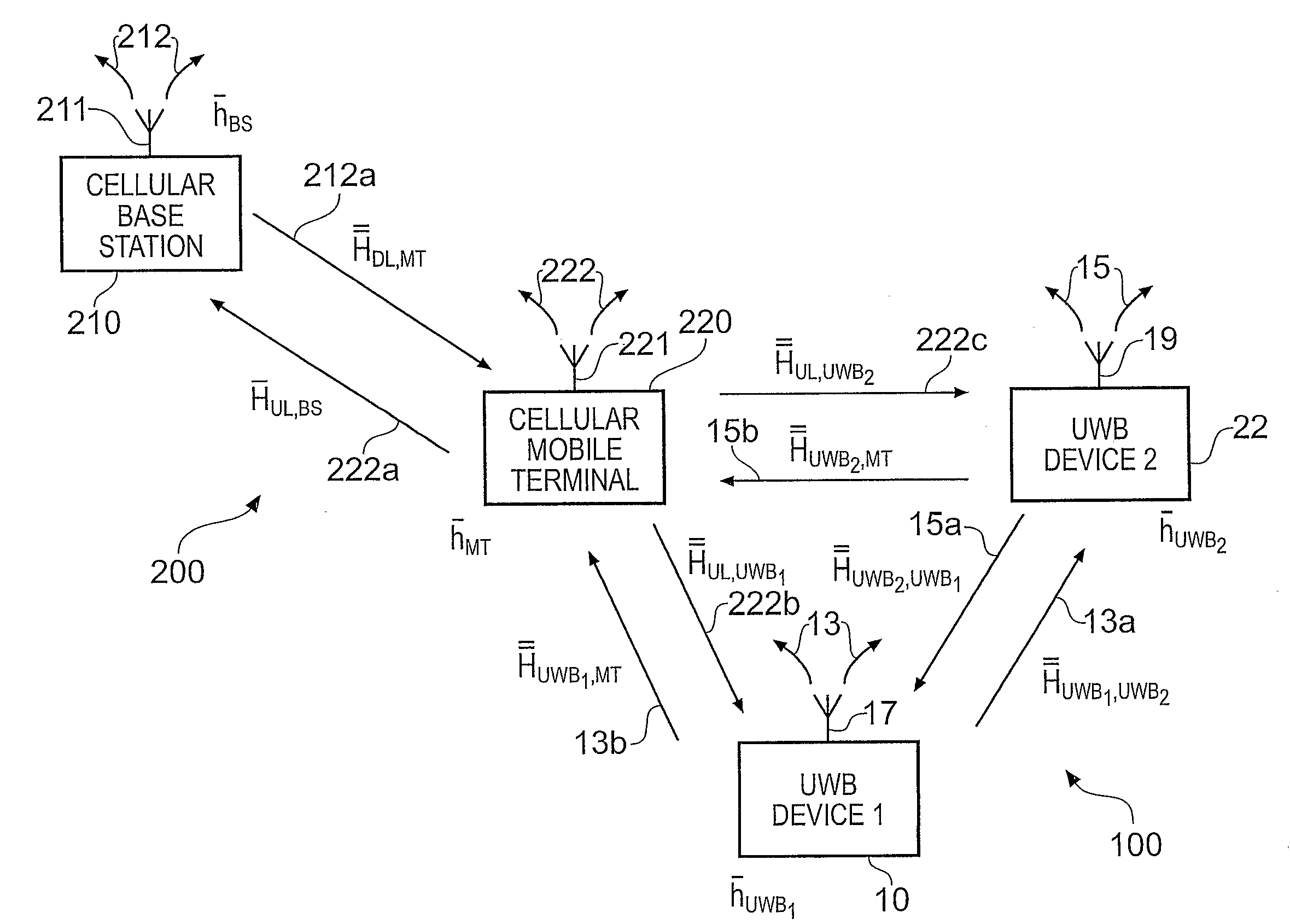
[0011]In embodiments of the present invention, a low power radio device is advantageously able to reduce the amount of interference it causes at a further radio device when it transmits a radio signal, by: a) detecting the polarization of an antenna of a further radio device, and b) controlling the polarization of a radio signal it transmits in dependence on the detected polarization.
[0015]Advantageously, in embodiments of the present invention, the amount of interference caused at a further radio device by an arrangement of low power radio devices may be reduced.
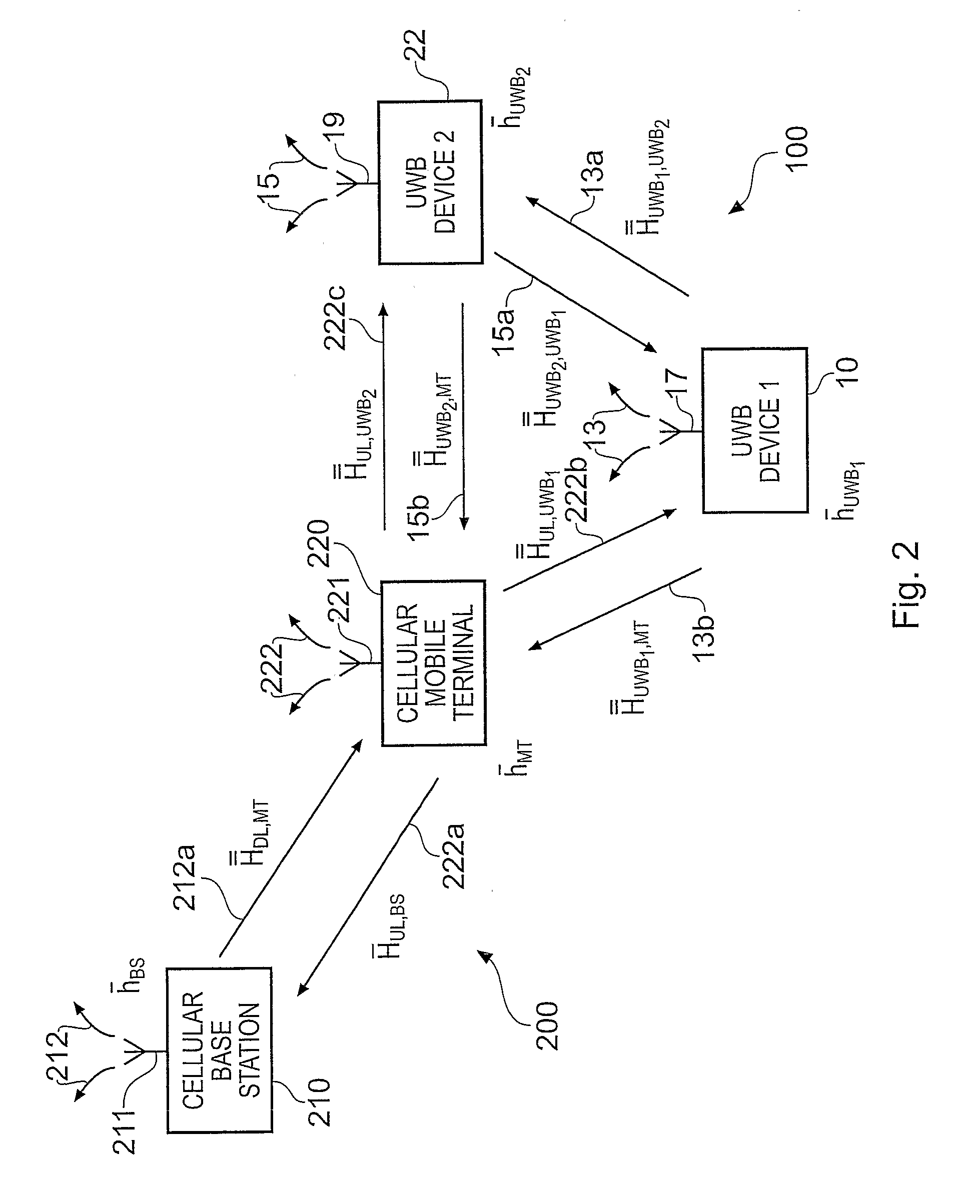
[0017]Advantageously, the controlling of the polarization of a transmitted radio signal by the first and second low power radio devices may lead to the radio signals transmitted by the first and second low power radio devices having substantially the same polarization, so the amplitude of the radio signals received at the second and first low power radio devices is maximised.

Problems solved by technology

As UWB devices may emit radiowaves in the frequency range 1 GHz to 3.1 GHz, they may cause interference to mobile terminals using some GSM frequencies, and / or some WCDMA frequencies and / or 802.11g frequencies or Bluetooth frequencies.
The large bandwidth used in UWB devices means that UWB transmissions having a centre frequency 500 MHz or more away from the GSM frequencies may still cause interference.
As UWB devices are allowed to operate in the frequency range of 3.1 GHZ to 10.6 GHz, it is envisaged that UWB devices may cause interference at 4G mobile terminals.

Method used


Image

  • Low Power Radio Device With Reduced Interference
  • Low Power Radio Device With Reduced Interference
  • Low Power Radio Device With Reduced Interference

Examples


Embodiment Construction

[0023]The Figures illustrate a low power radio device 10, operable in a first radio system 100, comprising: a detector 12, 14 for detecting the polarization of an antenna 221 of a further radio device 220, operating in a further radio system 200, different to the first radio system 100; and a transmitter 12 for controlling the polarization of a transmitted radio signal 13 in dependence on the detected polarization.

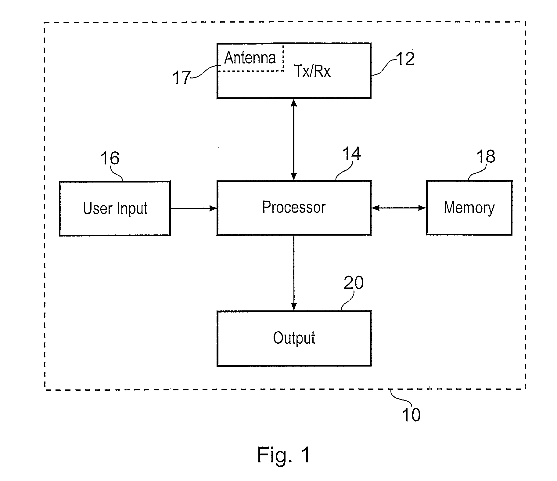
[0024]FIG. 1 is a schematic illustration of a UWB device 10. The UWB device 10 may be hand portable. The UWB device comprises a radio frequency transceiver 12, a processor 14, a user input 16, a memory 18 and an output 20.

[0025]The transceiver 12 comprises a transmitter, a receiver and an antenna 17 and is operable to transmit and receive UWB radio frequency signals. The processor 14 is connected to receive an input from the transceiver 12 and the user input 16 and to read from the memory 18, and to provide an output to the transceiver 12 and the output 20, and to write to...


PUM


Abstract

A low power radio device, operable in a first radio system, comprising: a detector for detecting the polarization of an antenna of a further radio device, operating in a further radio system, different to the first radio system; and a transmitter for controlling the polarization of a transmitted radio signal in dependence on the detected polarization. The polarization of the transmitted signal may be controlled to be substantially orthogonal to the polarization of the antenna of the further radio device.

Description

FIELD OF THE INVENTION[0001]Embodiments of the present invention relate to a low power radio device. In particular, they relate to a low power radio device for use in a radio system that operates using Ultra Wide Bandwidth (UWB) signals or any other wideband radio frequency system.BACKGROUND TO THE INVENTION[0002]UWB is a wireless radio technology. A UWB transmitter works by sending a signal across a very wide spectrum of frequencies. A corresponding receiver translates the signal into data. UWB technology may be defined as any radio technology having a spectrum that occupies a bandwidth greater than 20% of the centre frequency, or a bandwidth of at least 500 MHz.[0003]UWB is typically suited for transmitting data between consumer electronics, personal computers and mobile devices. UWB has the capacity to handle very high bandwidths of data, at very high speeds across short ranges. For example, UWB devices may be used to transport multiple audio or video streams.[0004]An example of ...

Claims


Application Information

Patent Timeline
Patent Type & Authority Applications(United States)
IPC IPC(8): H04B1/62H04J99/00
CPCH04B7/10Y02D70/442Y02D70/144Y02D70/142Y02D30/70
Inventor JUNTUNEN, JUHA O.
Owner NOKIA CORP
Learn More