Developing roller, electrophotographic process cartridge, and electrophotographic image forming apparatus

a development roller and process cartridge technology, applied in the field of developing rollers, electrophotographic process cartridges, electrophotographic image forming apparatus, can solve the problems of long time-consuming and laborious, affecting image quality and the lifetime of the photosensitive drum, and reliability problems, so as to achieve stably formed high-quality electrophotographic images, effective suppression of low molecular weight substances from elastic layers, and the effect of reducing labor intensity

Active Publication Date: 2008-12-25
CANON KK
View PDF4 Cites 12 Cited by
  • Summary
  • Abstract
  • Description
  • Claims
  • Application Information

AI Technical Summary

Benefits of technology

[0009]Also, the developing roller having the elastic layer may affect image quality and the lifetime of the photosensitive drum.
[0012]Then, with the intention of further stabilizing high-quality electrophotographic images according to contact development, the present inventors arrived at recognition that it is important to develop a developing roller having a surface layer that can effectively suppress the exudation of low molecular weight components from the elastic layer, has a surface excellent in toner release properties, and has sufficient flexibility, and does not easily cause cracks even when repeatedly subjected to image formation.
[0018]According to the developing roller of the present invention, the exudation of low molecular weight substances from the elastic layer can be effectively suppressed. In other words, even when the developing roller is contacted with an electrophotographic photosensitive member for a long time, the attachment of low molecular weight substances exuding from the elastic layer to the surface of the electrophotographic photosensitive body is effectively suppressed. As a result, high-quality electrophotographic images can be stably provided. Further, according to the developing roller of the present invention, filming on the surface of the developing roller is inhibited from occurring, so that images can be stably formed. Moreover, according to the developing roller of the present invention, peeling of the surface layer of the developing roller associated with use can be effectively suppressed. Therefore, a further improvement in the durability of the developing roller can be achieved.

Problems solved by technology

However, according to the study of the present inventors, the above-described inorganic particles were attached lightly to the surface, so that the inorganic particles were easily detached during use, and it was difficult to sustain the effect of suppressing filming for a long period.
Also, the developing roller having the elastic layer may affect image quality and the lifetime of the photosensitive drum.
It is described that in such a developing roller, there was a problem in reliability because the coating layer was insufficient in flexibility and adhesiveness to the elastic body.

Method used


Image

  • Developing roller, electrophotographic process cartridge, and electrophotographic image forming apparatus
  • Developing roller, electrophotographic process cartridge, and electrophotographic image forming apparatus
  • Developing roller, electrophotographic process cartridge, and electrophotographic image forming apparatus

Examples


manufacturing example 1

Manufacture of Elastic Roller 1

[0104]The following materials were blended to prepare a base material of liquid silicone rubber.

[0105]100 parts by mass of dimethylpolysiloxane having a vinyl group at both ends (vinyl group content: 0.15 mass %),

[0106]7 parts by mass of quartz powder as filler (trade name: Min-USil, manufactured by Pennsylvania Glass Sand), and

[0107]10 parts by mass of carbon black (trade name: DENKA BLACK, powdered product, manufactured by DENKI KAGAKU KOGYO KABUSHIKI KAISHA).

[0108]0.5 parts by mass of a complex of chloroplatinic acid and divinyltetramethyldisiloxane (0.5 mass %) as a curing catalyst was blended with the above base material to prepare a solution A. Also, 1.5 parts by mass of a dimethylsiloxane-methylhydrogensiloxane copolymer having a Si—H group at both ends (the content of H bonded to Si atoms: 0.30%) was combined with the above base material to prepare a solution B.

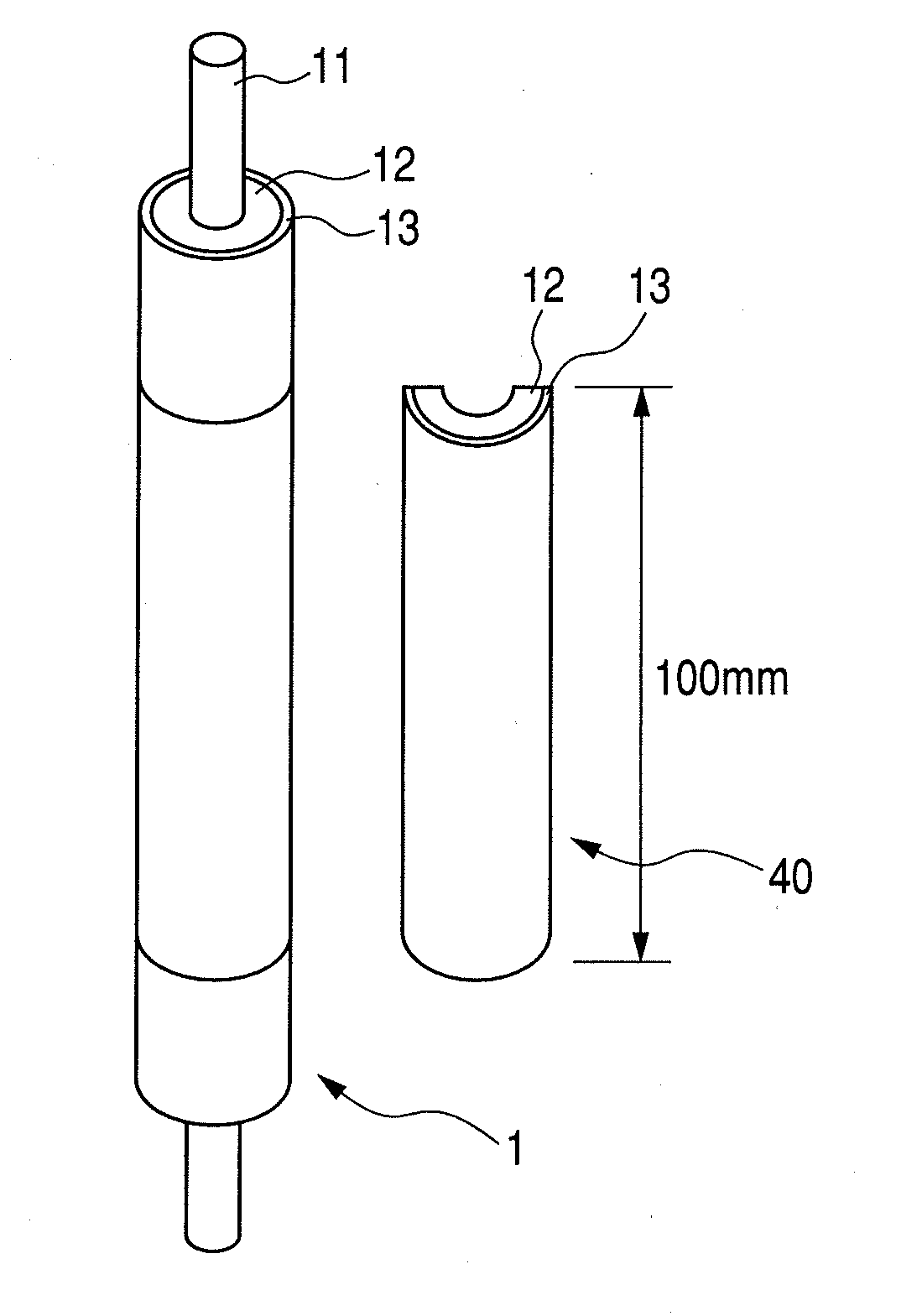
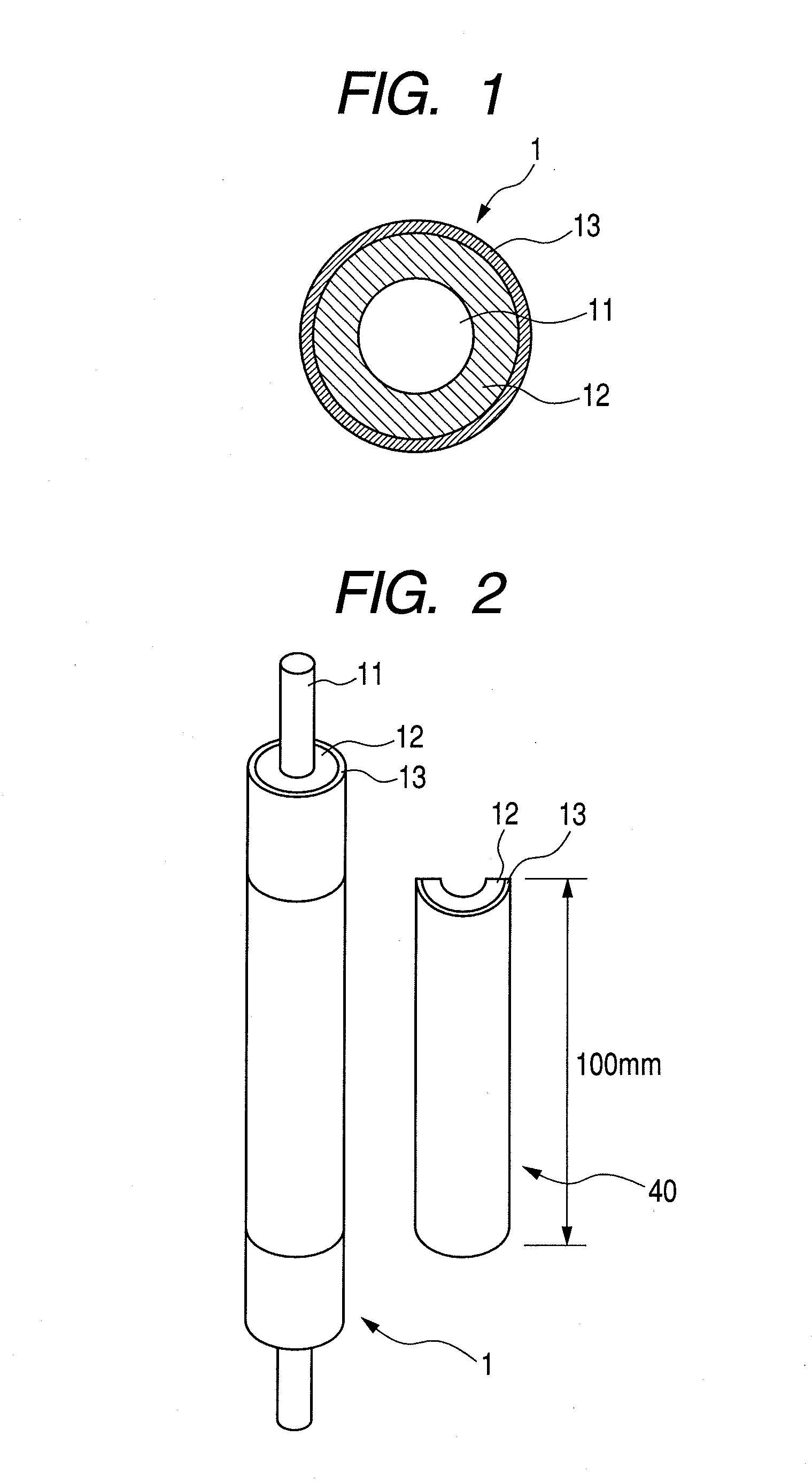
[0109]A columnar mandrel that was made of SUM material, had a diameter of 6 mm and a...

manufacturing example 2

Manufacture of Elastic Roller 2

[0110]The following materials were melted and kneaded, and extruded using a twin screw extruder having a diameter of 30 mm and an L / D of 32 to prepare a resin mixture.

[0111]100 parts by mass of a polyolefin elastomer (trade name: Santoprene 8211-25, manufactured by AES Japan), and

[0112]40 parts by mass of MT carbon black (trade name: Thermax Floform N990, manufactured by CANCARB).

[0113]Then, the above resin mixture was pelletized. A resin layer was formed from these pellets on an mandrel (diameter: 6 mm, and length: 250 mm), using a crosshead extruder. The ends of this resin layer were cut, and further, the resin layer portion was ground by a grindstone to produce an elastic roller 2 with an elastic layer having a thickness of 3 mm.

manufacturing example 3

Manufacture of Elastic Roller 3

[0114]An elastic roller 3 was produced in the same manner as in the above Manufacturing Example 2, except that the polyolefin elastomer (Santoprene 8211-25, manufactured by AES Japan) was changed to an olefin elastomer (trade name: Santoprene 8211-45, manufactured by AES Japan).


PUM


Abstract

A developing roller is provided having a surface that has excellent effect of suppressing exudation of low molecular weight substances from an elastic body, excellent toner release properties, and sufficient flexibility in which cracks do not easily occur even by repeated image formation. The developing roller carries and conveys toner to develop electrostatic latent images on a photosensitive drum with the toner and includes in this order a mandrel, an elastic layer, and a surface layer. The surface layer includes a silicon oxide film containing carbon atoms chemically bonded to silicon atoms. The silicon oxide film has an abundance ratio of oxygen atoms forming chemical bonds with silicon atoms to silicon atoms (O / Si) of 0.65 or more and 1.95 or less, and an abundance ratio of carbon atoms forming chemical bonds with silicon atoms to silicon atoms (C / Si) of 0.05 or more and 1.65 or less.

Description

[0001]This application is a continuation of International Application No. PCT / JP2008 / 057649, filed Apr. 15, 2008, which claims the benefit of Japanese Patent Application No. 2007-118781, filed Apr. 27, 2007.BACKGROUND OF THE INVENTION[0002]1. Field of the Invention[0003]The present invention relates to a developing roller used in an electrophotographic image forming apparatus, such as a copying machine and a laser printer, and an electrophotographic process cartridge and electrophotographic image forming apparatus which are provided with the developing roller.[0004]2. Related Background Art[0005]A contact development method in which a developing roller having an elastic layer is brought into contact with a photosensitive drum for development is proposed as a development method in which an electrostatic latent image on a photosensitive drum is visualized with a toner.[0006]The developing roller used for contact development is brought into contact with a contact member while conveying...

Claims


Application Information

Patent Timeline
Patent Type & Authority Applications(United States)
IPC IPC(8): G06F3/033
CPCG03G2215/0861G03G15/0818G03G21/186G03G2215/0863
Inventor ANAN, GENYAYAMAUCHI, KENICHISATOH, HIDENORI
Owner CANON KK
Why Eureka
Try Eureka