Swing Drive Device and Work Machine

a drive device and work machine technology, applied in lifting devices, soil shifting machines/dredgers, mechanical apparatus, etc., can solve the problems of substantial energy loss and energy loss, and achieve the effect of facilitating energy conservation by reducing the loss of hydraulic energy, smooth acceleration and efficient system

Inactive Publication Date: 2008-12-25
SHIN CATERPILLAR MITSUBISHI LTD CORP
View PDF1 Cites 46 Cited by
  • Summary
  • Abstract
  • Description
  • Claims
  • Application Information

AI Technical Summary

Benefits of technology

[0017]According to the present invention as claimed in claim 1, the hydraulic motor and the electric motor are capable of simultaneously driving the swing unit. Therefore, when accelerating swinging action, smooth acceleration can be achieved by controlling electric current to the electric motor, thereby enabling energy conservation by reducing loss of the hydraulic energy that is discharged as thermal energy into the air when the load pressure to the hydraulic motor is controlled. During deceleration of swinging action, loss of the hydraulic energy that is discharged as thermal energy into the air when the load pressure to the hydraulic motor is controlled can be reduced by transforming swinging motion energy to electric energy by means of the electric motor and storing the electric energy in the electric energy storage device. Thus, an efficient system can be constructed. Furthermore, the combination of the hydraulic motor and the electric motor enables the components to be made compact, resulting in cost reduction. During fine operation, it is possible to drive the swing unit solely by the electric motor, without actuating the hydraulic motor, by controlling the no-load valve at an open position.
[0018]According to the present invention as claimed in claim 2, the inverter is capable of functioning so that the electric motor functions as a generator during normal swinging action and thereby charges the electric energy storage device depending on the level of charge of the electric energy storage device while the hydraulic motor is driving the upper structure and that, during deceleration of swinging action, the electric motor functions as a generator, thereby transforming swinging motion energy to electric energy to charge the electric energy storage device.
[0019]According to the present invention as claimed in claim 3, should swinging motion energy during deceleration of swinging action exceed the capacitor of the electric motor as the generator, the relief valves provided for the hydraulic motor function as safety valves, thereby protecting the electric motor.
[0020]According to the present invention as claimed in claim 4, the hydraulic motor and the electric motor can be simultaneously driven to rotate the upper structure on the lower structure. Therefore, when accelerating swinging action, i.e. rotation of the upper structure, smooth acceleration can be achieved by controlling electric current to the electric motor, thereby enabling energy conservation, in other words reducing loss of the hydraulic energy that is discharged as thermal energy into the air when the load pressure to the hydraulic motor is controlled. During deceleration of swinging action, i.e. rotation of the upper structure, loss of the hydraulic energy that is discharged as thermal energy into the air when the load pressure to the hydraulic motor is controlled can be reduced by transforming swinging motion energy to electric energy by means of the electric motor and storing the electric energy in the electric energy storage device. Thus, an efficient system can be constructed. Furthermore, as the combination of the hydraulic motor and the electric motor enables the components to be made compact, costs can be reduced, resulting in a reduction in production costs for the work machine.

Problems solved by technology

Such energy loss is substantial when conducting swinging operation alone.
At that time, too, the relief valve 28B transforms hydraulic energy to thermal energy in the same manner as it does during acceleration, and the thermal energy is discharged into the air through the oil cooler 29, resulting in energy loss.

Method used


Image

  • Swing Drive Device and Work Machine
  • Swing Drive Device and Work Machine
  • Swing Drive Device and Work Machine

Examples


Embodiment Construction

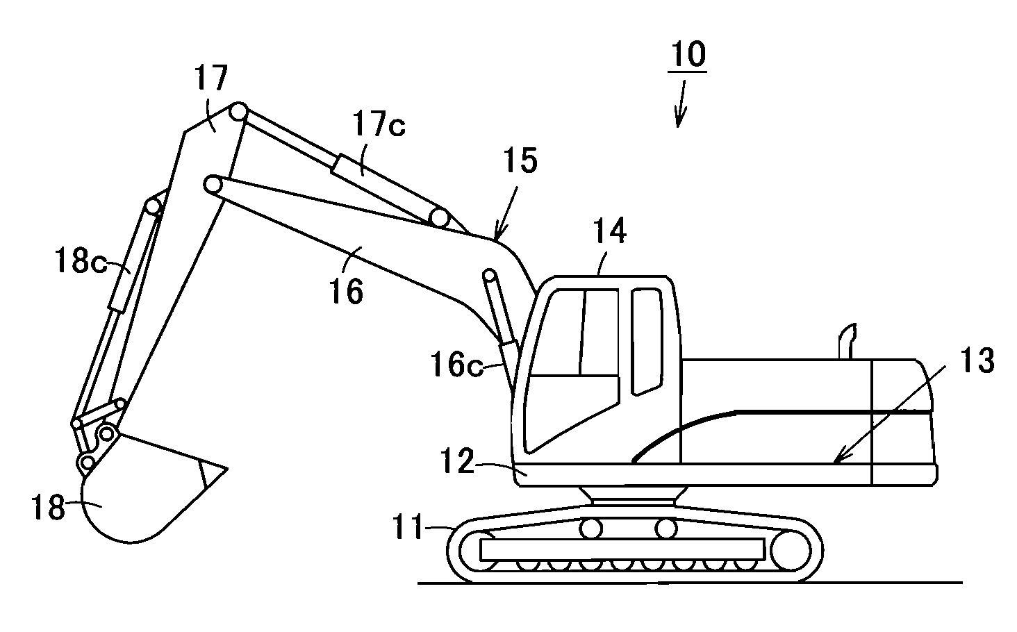
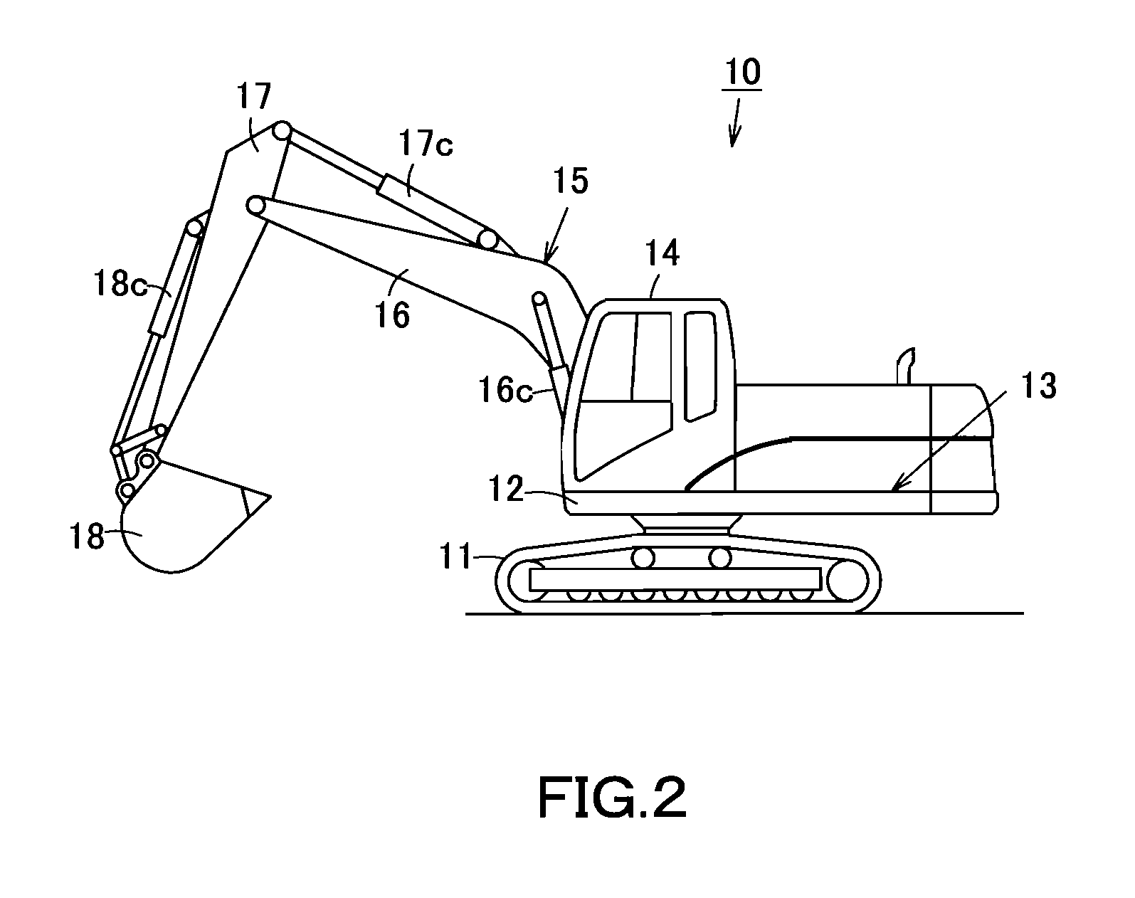
[0037]Next, the present invention is explained in detail hereunder, referring to an embodiment thereof shown in FIG. 1. The swing type work machine 10 shown in FIG. 2 also depicts a work machine according to the present invention.

[0038]As shown in FIG. 2, an upper structure 12 adapted to be rotated by a swing drive device 30 shown in FIG. 1 is mounted on a lower structure 11. A work equipment 15 is mounted on the upper structure 12. As the work equipment 15 and other components have already been described, their explanations are omitted herein.

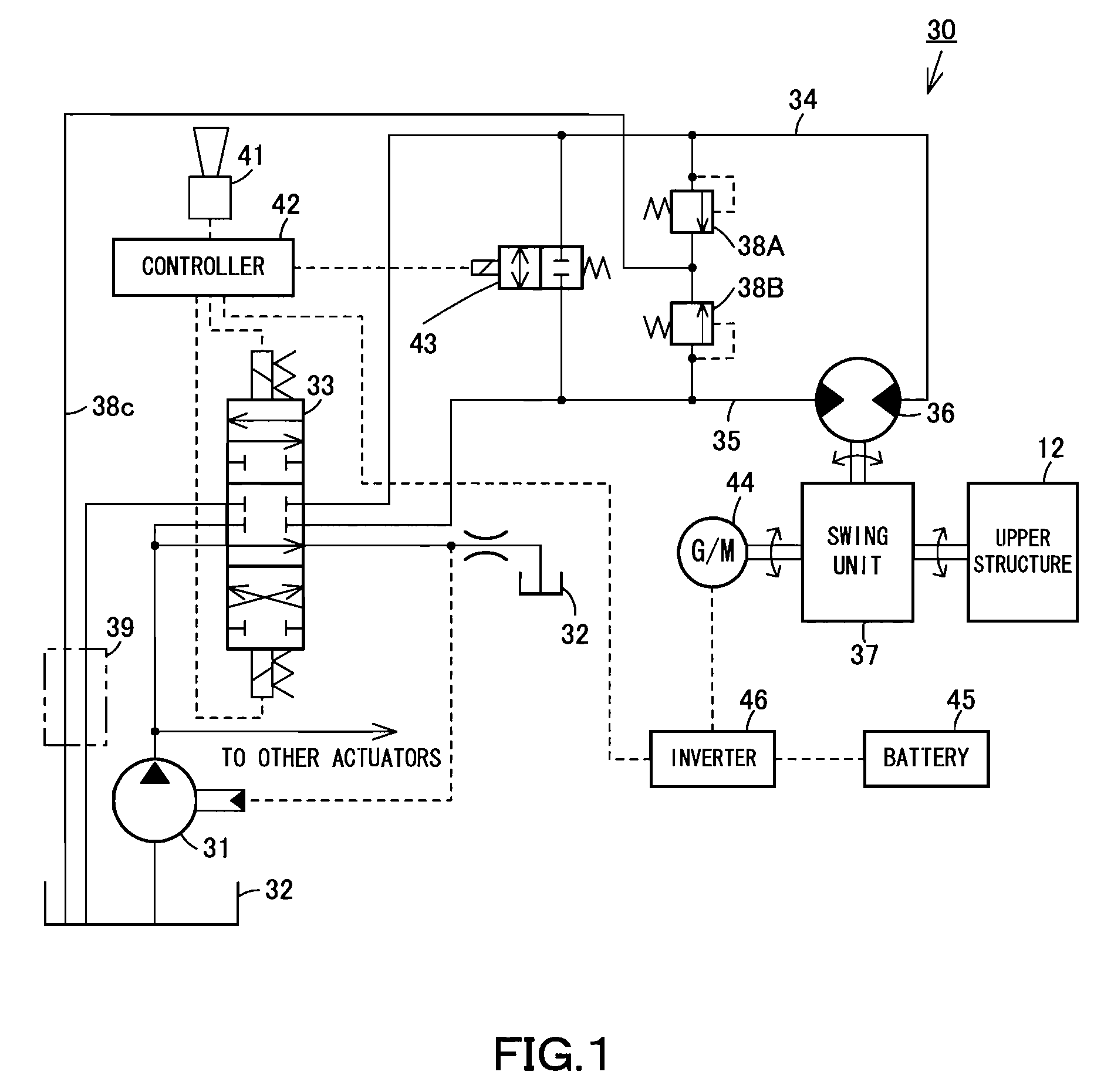
[0039]The swing drive device 30 shown in FIG. 1 includes a hydraulic fluid pressure circuit, which may be an oil hydraulic circuit. The hydraulic fluid pressure circuit has a hydraulic pump 31 that is mounted on the upper structure and serves as a hydraulic pressure source, such as a pressure oil source. A discharge passage and a return passage of the hydraulic pump 31 are respectively connected to a supply port and a return port of a control ...


PUM


Abstract

The invention provides a swing drive device that is capable of energy conservation by limiting loss of hydraulic fluid pressure energy resulting from discharge of the hydraulic fluid pressure energy as thermal energy into the air during acceleration or deceleration of swinging action and transforming motion energy to electric energy during deceleration of swinging action, and also enables cost reduction by making components and parts compact.

Description

TECHNICAL FIELD[0001]The present invention relates to a swing drive device adapted to be operated by hydraulic fluid pressure energy and electric energy. The present invention also relates to a work machine equipped with such a swing drive device.BACKGROUND ART[0002]FIG. 2 shows a swing type work machine 10, which is a hydraulic excavator. The work machine 10 has a machine body including a lower structure 11 and an upper structure 12, which is revolvably mounted on the lower structure 11. A cab14 and a work equipment 15 are mounted on the machine body 13. The work equipment 15 includes a boom 16, an arm connected to the distal end of the boom 16, and a bucket connected to the distal end of the arm 17. The boom 16 is adapted to be vertically pivoted by boom cylinders 16c. The arm 17 and the bucket 18 are adapted to be respectively rotated by a stick cylinder 17c and a bucket cylinder 18c. [0003]A swing system hydraulic circuit for rotating the upper structure 12 on the lower structur...

Claims


Application Information

Patent Timeline
Patent Type & Authority Applications(United States)
IPC IPC(8): B66C23/06
CPCE02F9/128E02F9/2075E02F9/2217F15B21/14F15B2211/3111F15B2211/31576F15B2211/327F15B2211/50527F15B2211/7058F15B2211/88
Inventor MORIYA, NAOYUKIWADA, ATSUSHIBINNAKA, MADOKA
Owner SHIN CATERPILLAR MITSUBISHI LTD CORP
Why Eureka
Try Eureka