Spring System for a Vehicle Wheel Suspension System

Active Publication Date: 2009-01-01
BAYERISCHE MOTOREN WERKE AG
View PDF3 Cites 6 Cited by
  • Summary
  • Abstract
  • Description
  • Claims
  • Application Information

AI Technical Summary

Benefits of technology

[0003]Chassis of motor vehicles can be designed according to different philosophies. Comfortably designed chassis of passenger cars are relatively soft; chassis of a sportier design are relatively hard. In addition to the different philosophy of the individual manufacturers of automobiles or passenger cars, in the case of some vehicles, a “sporty chassis” may be chosen as optional equipment. In order to design this selection in the respective vehicle in a variable fashion, some manufacturers offer so-called adjusting shock absorbers by which the driver can choose between a comfortable and a sporty shock absorber coordination. Although this different shock absorber adjustment has a subjective influence on the driver's feelings, objectively no improvement can be achieved with respective to a sportier vehicle handling when the damping is hard. An adjusting possibility of the spring rate(s) would be more favorable here.
[0004]The latter is basically known for vehicles; compare, for example, the second document mentioned above which, however, shows a relatively high-expenditure controllable suspension system for wheel suspension on motor vehicles. In contrast, a variable suspension system for a motor vehicle having at least one main spring element and at least one shock absorber described in the initially first-mentioned German Patent Document DE 10 2004 013 559 B4 is simpler. The main spring element consists of a bearing spring and as usual of a pressure addition spring as well as a tension stop spring. In addition, a second spring element is provided which counteracts or can counteract the main spring element and can be optionally activated for this purpose by way of an adjusting system, the engaged second spring element causing a spring rate intensification by a premature intervention of the pressure addition spring present in the compression direction and a lowering of the motor vehicle. According to this known state of the art, the pressure addition spring therefore always has to be in an engagement when an increased spring rate is desired. Since, however, a pressure addition spring is also used as an end stop for limiting

Problems solved by technology

Although this different shock absorber adjustment has a subjective influence on the driver's feelings, objectively no improvement can be achieved with respective to a sportier vehicle handling when the damping is hard.
Since, however, a pressure addition spring is also used as an end stop for limiting the spring excursion of the bearing spring

Method used


Image

  • Spring System for a Vehicle Wheel Suspension System
  • Spring System for a Vehicle Wheel Suspension System
  • Spring System for a Vehicle Wheel Suspension System

Examples


Embodiment Construction

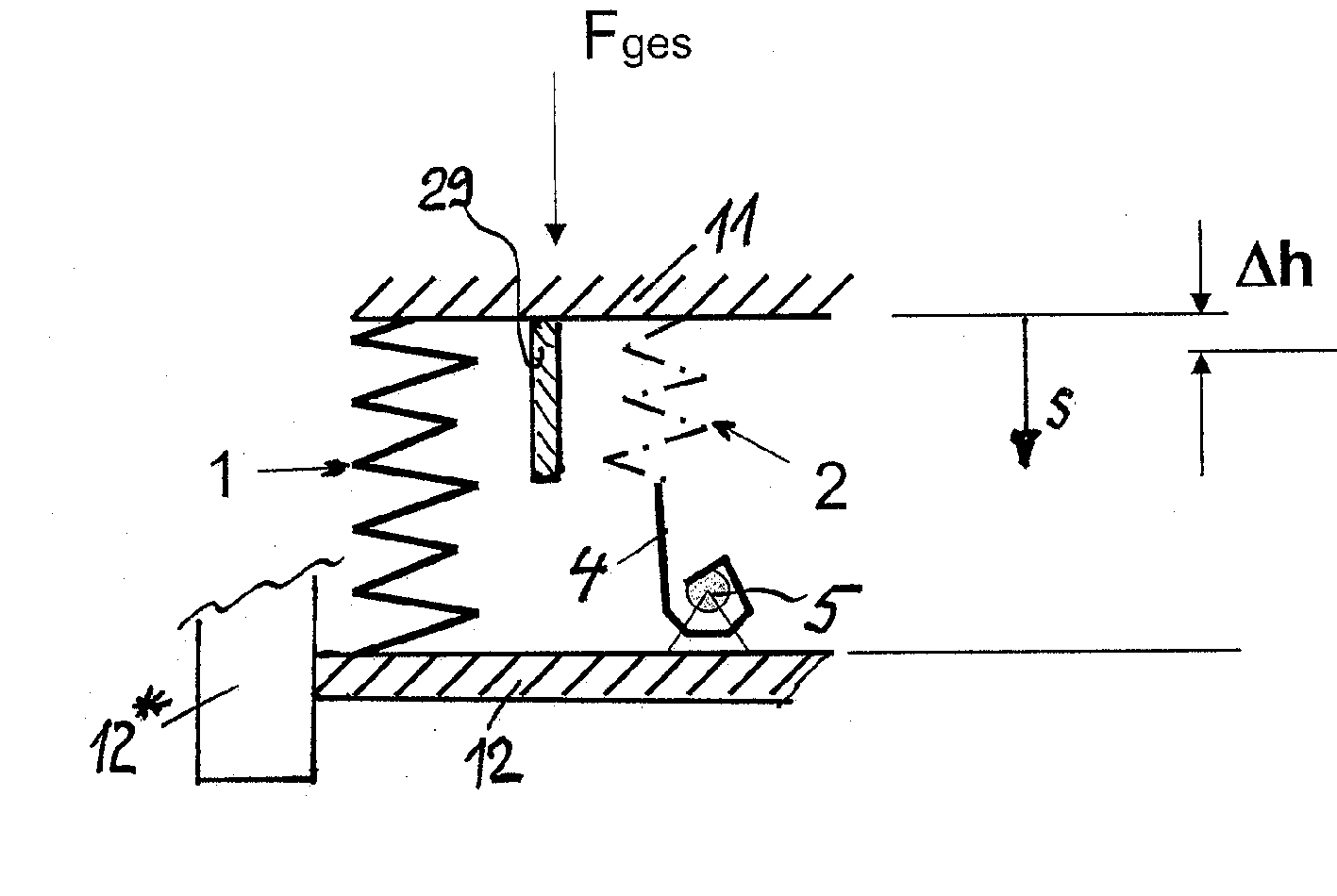
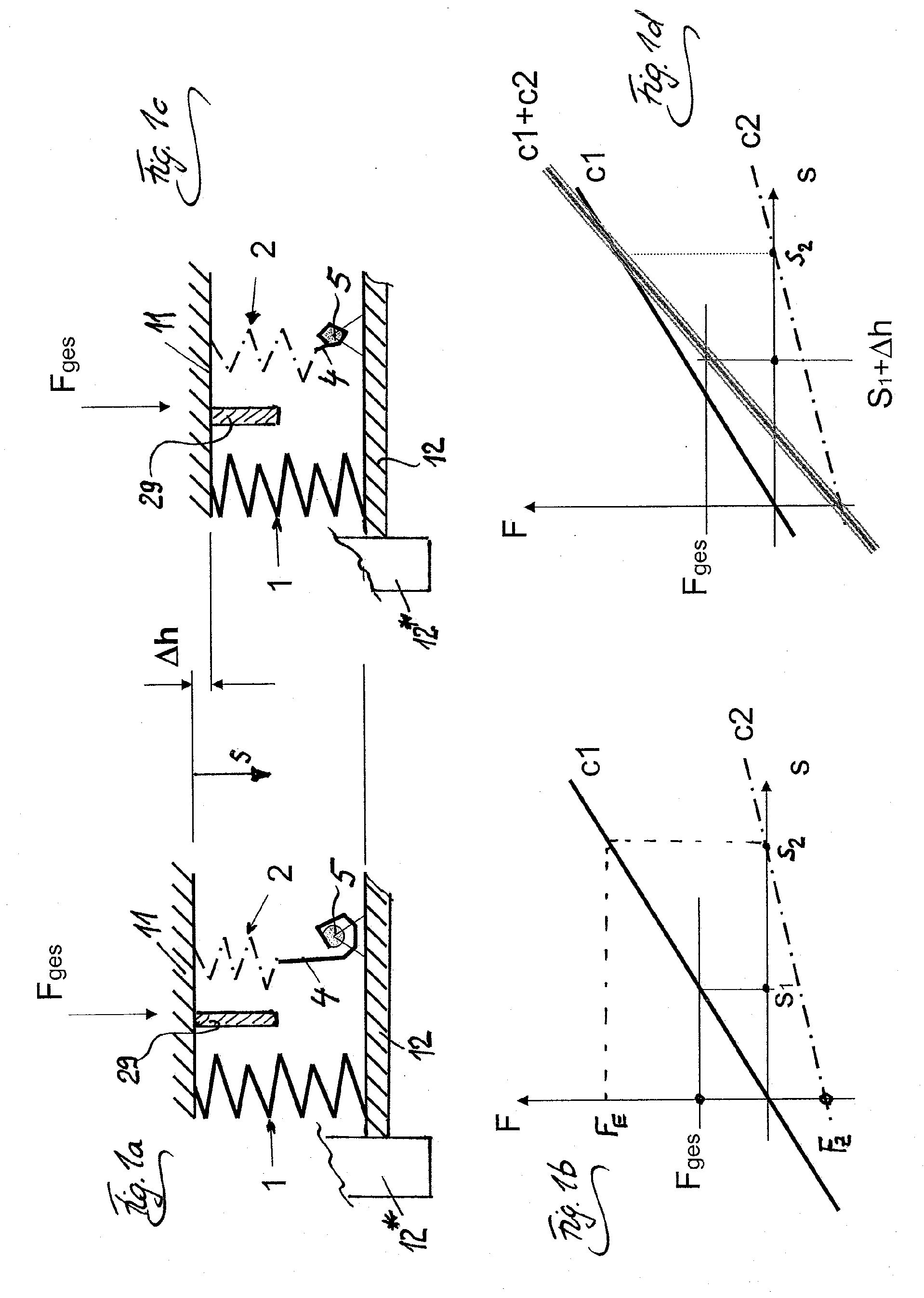
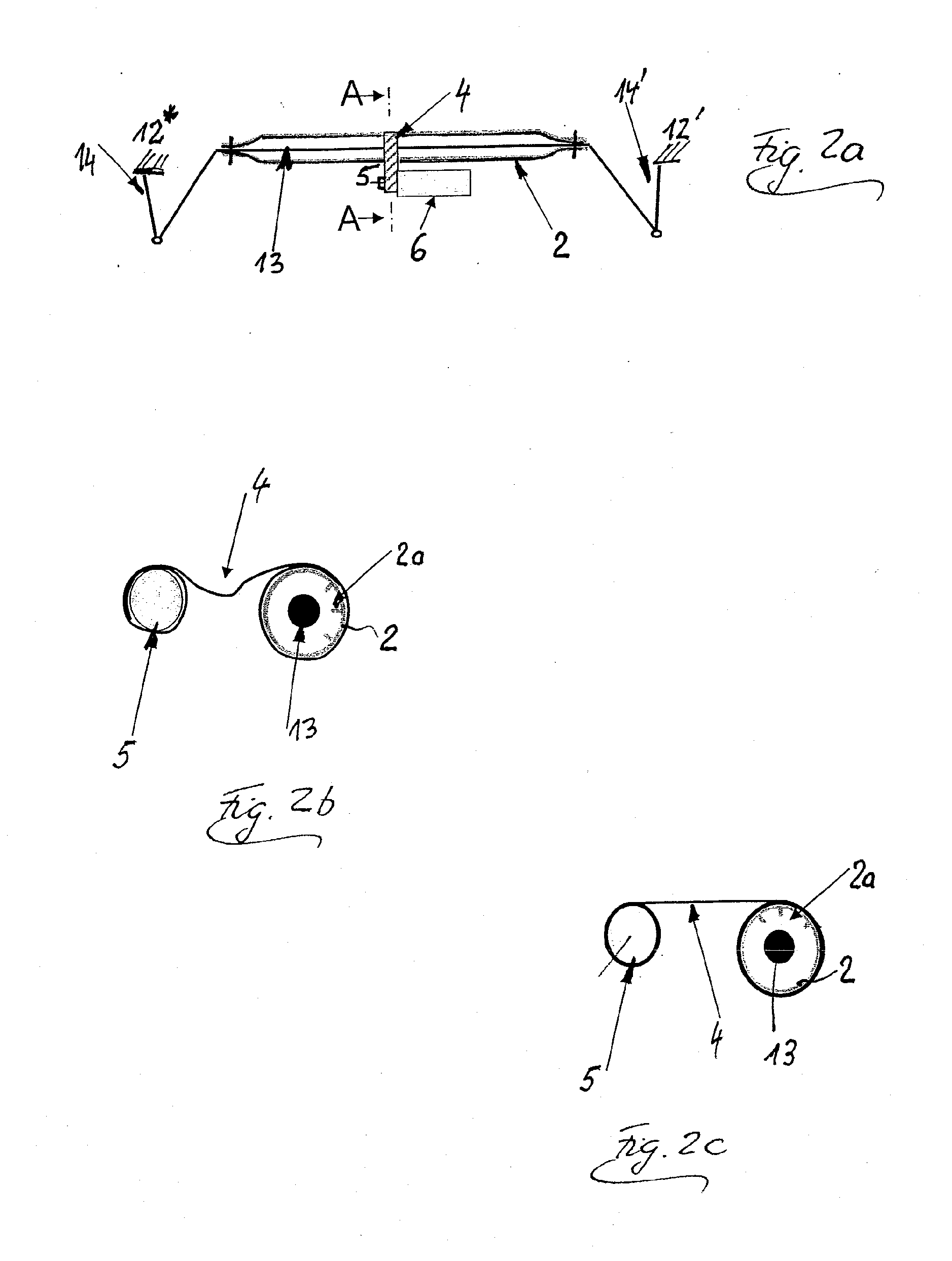
[0011]FIG. 1a shows a first spring element 1 which is always clamped in between two only abstractly illustrated components, which concretely are or may be a lower control arm 12 guiding the wheel 12* (more precisely, its wheel carrier) of a double-track vehicle (which control arm is known to a person skilled in the art), and the body 11 of the vehicle, which first spring element 1 is constructed as a coil pressure spring and acts as a bearing spring for the body 11 with respect to the wheel 12* and thereby in the end is clamped between the body 11 and the wheel 12*. In addition to this first spring element 1, a second spring element 2 can be clamped between these components; that is, between the control arm 12 (or, in the end, the wheel 12*) and the body 11 by means of a mechanical tension device, which in this case consists of a flexible tension device 4, which can be wound onto a reel 5 or unwound from the latter. For this purpose, the reel 5 is fastened to one of the two componen...


PUM


Abstract

The invention relates to a suspension system for a vehicle wheel suspension having a first spring element (1) in the end clamped between the vehicle body (11) and a vehicle wheel (12,12′) and a second or additional spring element (2,3) which in the end can be clamped between the vehicle body (11) and the vehicle wheel (12,12′) by the introduction of a tensile force by means of a mechanical tensioning element (4,5,6,20), which spring element (2,3) can thereby be connected parallel to the first spring element (1), while this additional spring element (2,3) is not active without tensile force introduced into the system, and furthermore having a pressure addition spring element (29) which, in the case of large spring excursions of the first spring element (1), becomes active by way of an end stop. In this case, the pressure addition spring element (29) is not activated with the introduction of the tensile force for activating the second or additional spring element (2). The spring rate of the second spring element (2) is preferably lower than that of the first spring element (1). Second or additional spring elements assigned to different wheels or axles of the motor vehicle can be activated or deactivated by means of a common mechanical tensioning element having a servo motor which can shorten or lengthen several tension devices connected with the additional spring elements and, for this purpose, can wind them onto reels or unwind them from the latter.

Description

CROSS-REFERENCE TO RELATED APPLICATIONS[0001]This application is a continuation of PCT International Application No. PCT / EP2007 / 001100, filed on Feb. 9, 2007, which claims priority under 35 U.S.C. §119 to German Application No. 10 2006 011 856.1, filed Mar. 15, 2006, the entire disclosures of which are expressly incorporated by reference herein.BACKGROUND AND SUMMARY OF THE INVENTION[0002]The invention relates to a suspension system for a vehicle wheel suspension having a first spring element in the end clamped between the vehicle body and a vehicle wheel and a second or additional spring element which in the end can be clamped between the vehicle body and the vehicle wheel by the introduction of a force or of a momentum by a mechanical tensioning element, which spring element can thereby be connected parallel to the first spring element, while this additional spring element is not active without force or momentum introduced into the system, and furthermore having a pressure additio...

Claims


Application Information

Patent Timeline
IPC IPC(8): G01M17/04
CPCB60G11/50B60G17/021B60G17/025B60G2500/20B60G2202/12B60G2202/135B60G2202/42B60G21/0558
Inventor PRUCKNER, ALFRED
Owner BAYERISCHE MOTOREN WERKE AG
Why Eureka
Try Eureka