Vaporizer and Processor

a technology of vaporizer and processor, which is applied in the direction of coating, chemical vapor deposition coating, metallic material coating process, etc., can solve the problems of gas not reaching, small amount of so-called dead space, and remaining unvaporized in the vaporization chamber, etc., and achieves the effect of solving small amount of dead spa

Inactive Publication Date: 2009-01-01
TOKYO ELECTRON LTD
View PDF4 Cites 18 Cited by
  • Summary
  • Abstract
  • Description
  • Claims
  • Application Information

AI Technical Summary

Benefits of technology

[0006]The present invention has been developed to effectively solve the aforementioned drawbacks. It is, therefore, an ob

Problems solved by technology

However, when the carrier gas is supplied into the vaporization chamber as described above, there exists a small amount of so called dead space, i.e., an area where the carrier gas does not reach sufficiently.
The liquid source material coming

Method used


Image

  • Vaporizer and Processor
  • Vaporizer and Processor
  • Vaporizer and Processor

Examples


Embodiment Construction

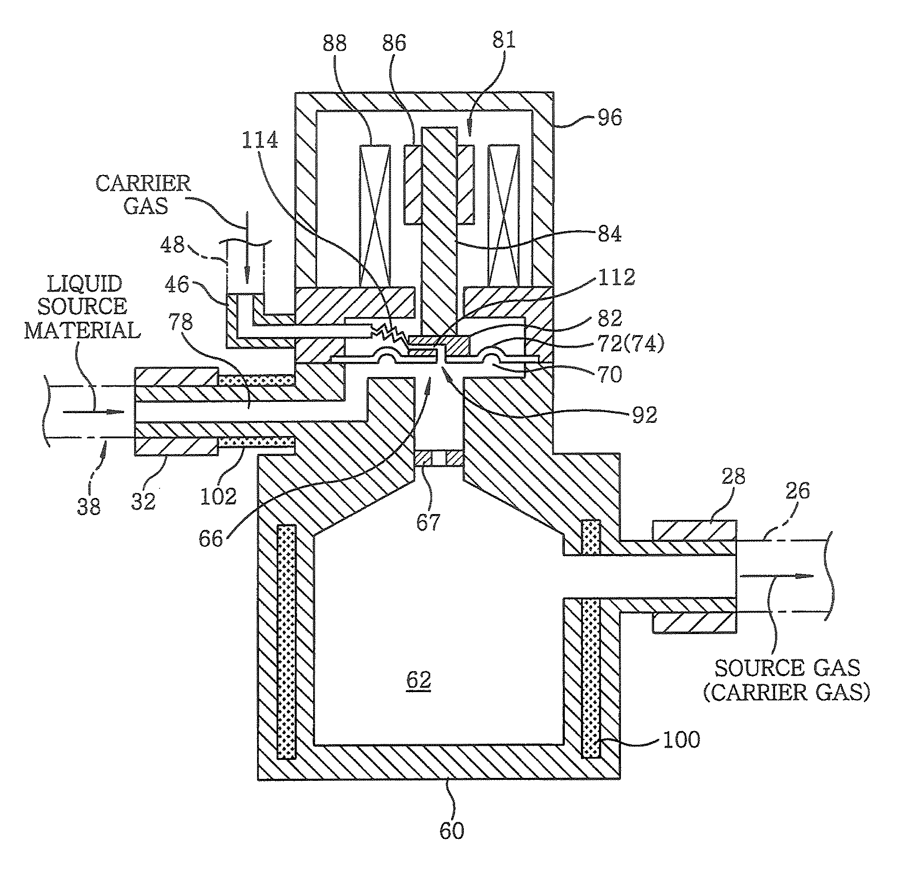
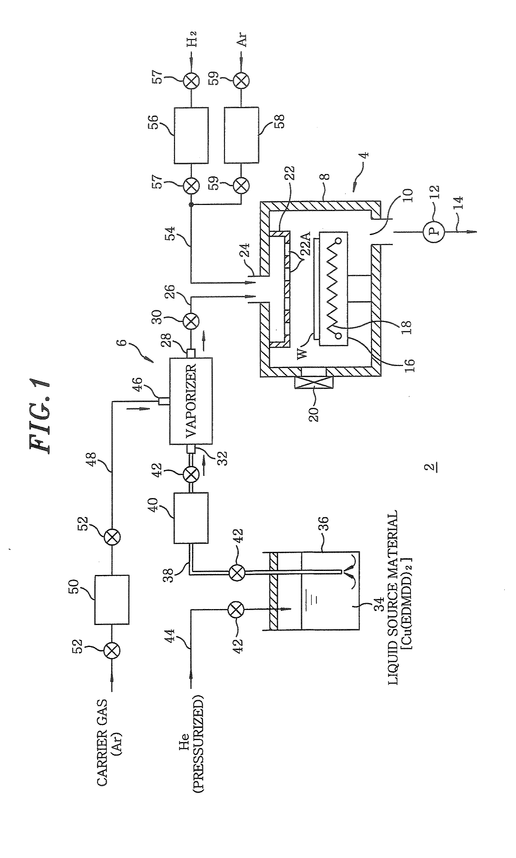
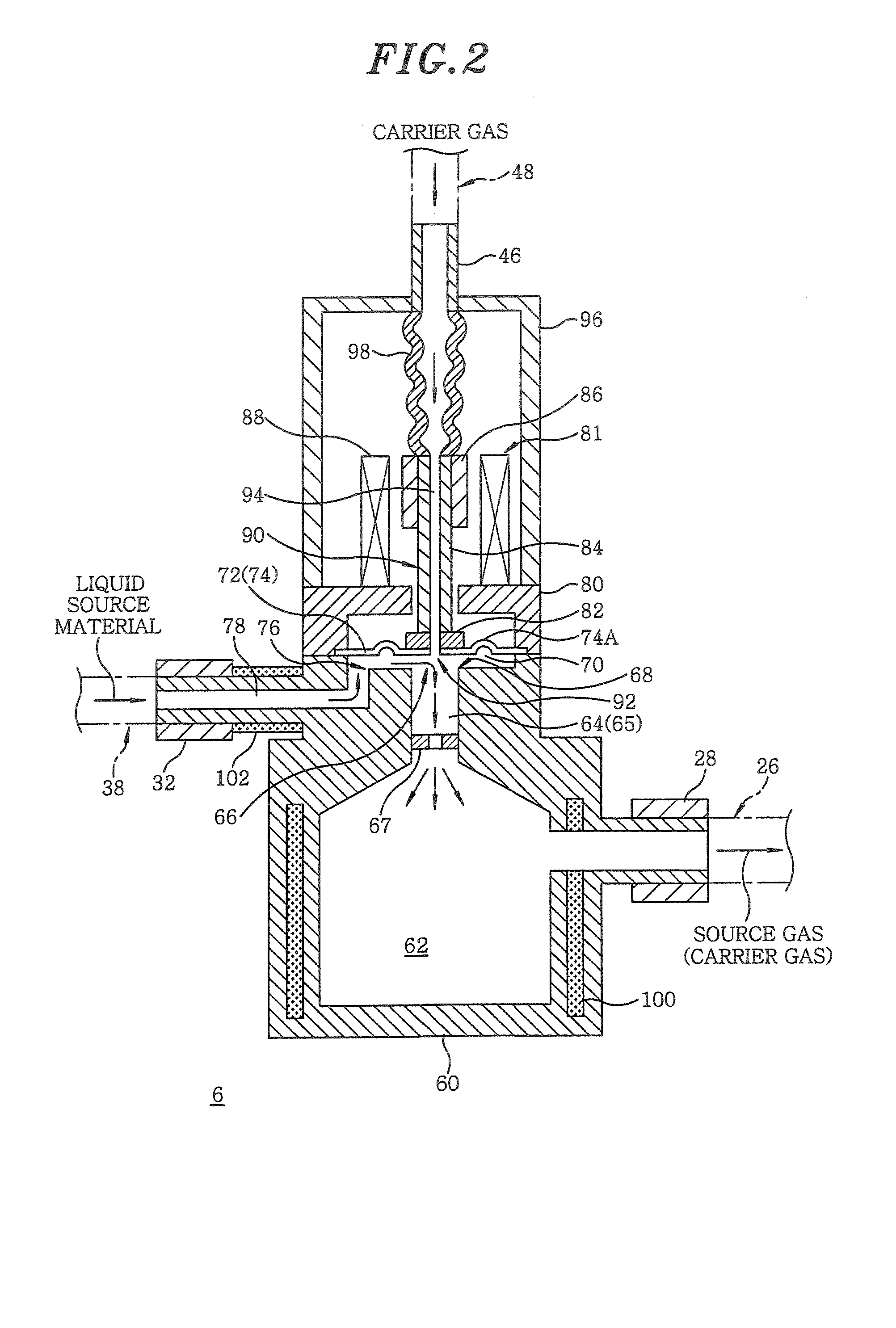
[0051]Hereinafter, a vaporizer and a processing apparatus in accordance with an embodiment of the present invention will be described with reference to the accompanying drawings. FIG. 1 is a schematic system diagram showing an entire configuration of a film forming apparatus, which is one example of the processing apparatus of the present invention. FIG. 2 describes a cross sectional view illustrating a structure of the vaporizer of the present invention. FIG. 3 provides a cross sectional view showing the vaporizer of FIG. 2 in the state that a valve port is closed by a valve body. FIG. 4 presents a top view of a liquid reservoir chamber of the vaporizer of FIG. 2; and FIG. 5 represents a bottom view of the valve body of the vaporizer of FIG. 2.

[0052]To begin with, the entire configuration of a film forming apparatus will be described with reference to FIG. 1. The film forming apparatus illustrated herein is for forming a Cu film as a metal film through a CVD process by using a liqu...


PUM


Abstract

A vaporizer for vaporizing a force-fed liquid source material in a depressurized atmosphere to generate a source gas and discharging the source gas together with a carrier gas, the vaporizer includes a liquid reservoir chamber for temporarily storing the force-fed liquid source material; a vaporization chamber communicating with the liquid reservoir chamber via a valve port. Further the vaporizer includes a valve body adapted to sit on a vale seat surrounding the valve port of the liquid reservoir chamber; an actuator for driving the valve body; a carrier gas injection hole formed at a side of the valve body facing the valve port; and a discharge port for discharging the source gas from the vaporization chamber. By virtue of a specific arrangement of the carrier gas injection hole, the liquid source material is prevented from remaining unvaporized at a downstream side of the valve port.

Description

FIELD OF THE INVENTION [0001]The present invention relates to a processor for performing a specific treatment, e.g., a film forming process or the like, on a target object, e.g., a semiconductor wafer or the like and a vaporizer for vaporizing a liquid source material for use in the specific treatment.BACKGROUND OF THE INVENTION [0002]In general, in order to manufacture a semiconductor integrated circuit or the like, a target object such as a semiconductor wafer or the like is repeatedly subjected to various processes such as a film forming process, an etching process, an oxidation / diffusion process, a reduction process and the like. Recently, various metal films such as Ta, Ti, Cu and the like are formed by the film forming process. In order to form such metal films, there is widely used a liquid source material having a low vapor pressure and a liquid state at room temperature and one atmospheric pressure. The liquid source material is force-fed to a vaporizer and then is vaporize...

Claims


Application Information

Patent Timeline
IPC IPC(8): H01L21/306C23C16/54
CPCC23C16/4482C23C16/18C23C16/448
Inventor KOJIMA, YASUHIKOHOSHINO, TOMOHISA
Owner TOKYO ELECTRON LTD
Why Eureka
Try Eureka