[0005]It is the object of the present invention to provide a ball pin for ball joints with
high load-
bearing capacity, so as to particularly be useful in the suspension of a motor vehicle, which ball pin can be manufactured at low cost and which makes possible a high level of joint ball customization.
[0006]According to the invention, a metallic ball pin is provided for use in a
ball joint in the suspension of motor vehicles. The ball pin has a pin member with a joint ball core portion on one end of the pin member and a pin end on the other. The pin member has a pin outer surface and a longitudinal axis. The joint ball core portion has a surface portion that extends radially outwardly with respect to the longitudinal axis of the pin member and with respect to an adjacent surface portion to create a core contour. The joint ball core portion is the region that receives and supports a ball surface part. The ball surface part is molded and formed around the joint ball core portion using an
injection molding process. The
injection molding process allows for material optimization in terms of strengths,
machine-ability, and other material properties since a greater array of materials are available. The design of the ball pin using the injection molding process allows for two different distinct parts (the joint ball core portion and the ball surface part) to permanently attach making it possible to combine ball surface parts with different shaped pin members to create a
modular system. Furthermore, this design results in considerably reducing manufacturing costs since
machining of the ball pin is simplified and makes it possible to use variable pin diameters, which leads to longer service of the ball pin.
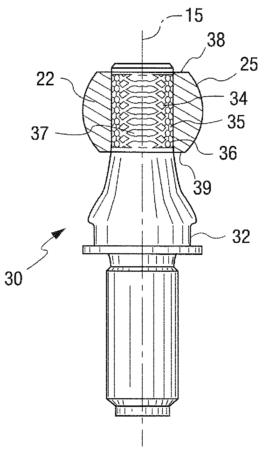
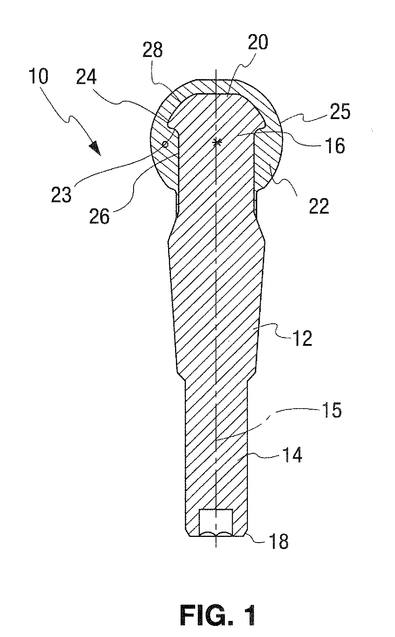
[0008]The pin member advantageously includes a backing surface at the joint core portion. The backing surface may be a knurled surface or a similar holding function of a joint ball core region of the pin member providing a positive locking between the pin member and ball surface part material. The knurled surface includes surface portions that extend radially outwardly with respect to the longitudinal axis of the pin member and radially outwardly with respect to an adjacent core surface region. The joint ball core region may have a top surface portion perpendicular to a longitudinal axis of the pin member. Optionally, the ball surface part may or may not be in contact with the top surface of the joint ball core region. The joint ball core region may be
mushroom shaped providing good positive locking. The joint ball core region may also be somewhat ball shaped with the molded or deposited outer material forming the
ball bearing surface. Furthermore, the joint ball core region may have concave shaped side surfaces that transition to a
flange edge for better positive locking. The joint ball core region may also have a circumferential side
edge surface that extends substantially perpendicular to a longitudinal axis of the pin member to provide better positive locking.
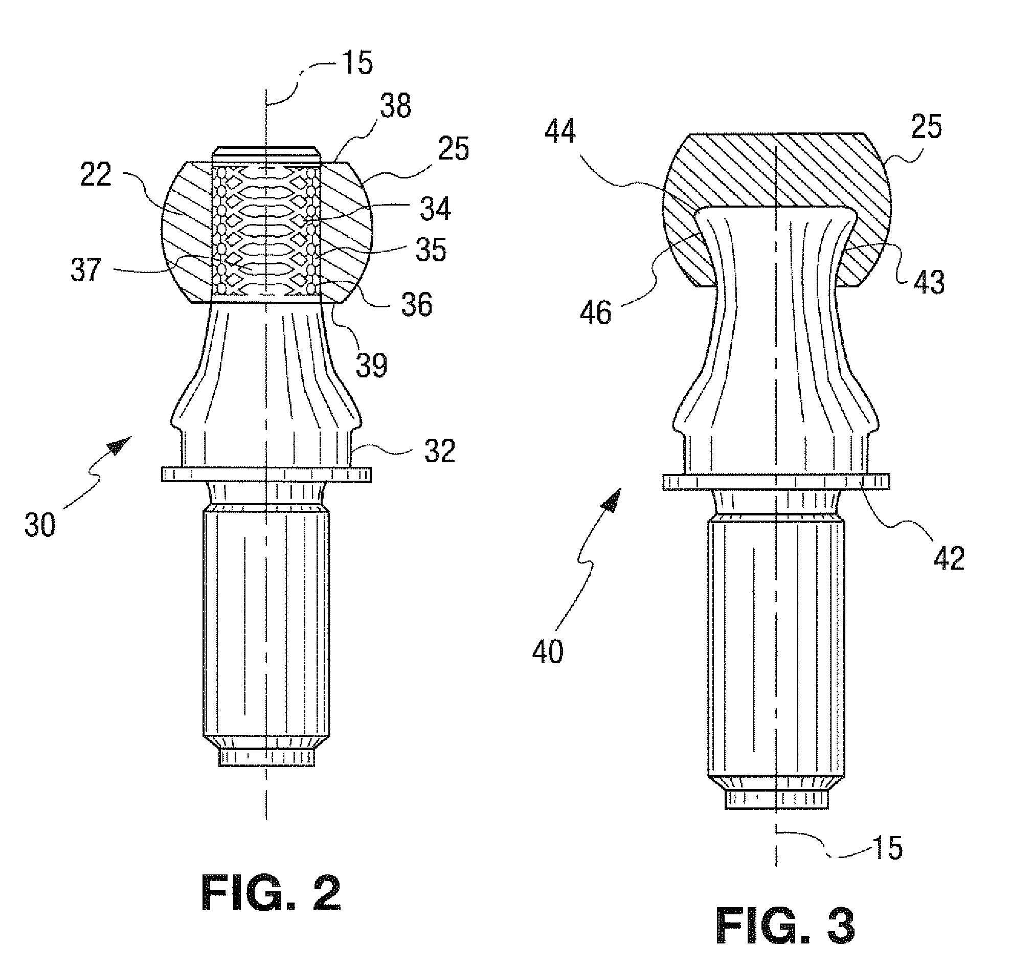
[0009]By forming the ball as a molded surface, the various shape aspects of the outer surface may be controlled based on the mold used. The molded joint ball surface allows joint ball surfaces to be created with constant ball dimensions. Constant ball dimensions make it possible to considerably reduce the expense of machining and to improve the quality of the joint ball
surface shape since secondary operations can be performed, such as
induction hardening, prior to formation of the ball to help avoid heat
distortion of the ball shape. Numerous features can also be incorporated into the injected areas, such as support rings for boots, seal grooves, and customized ball shapes, which can include
equator clearances for torque control and
grease grooves. Furthermore, both the ball surface part and the pin member are formed of a metallic
metal and are therefore capable of being used in joints with
high loading-bearing capacity. The joint ball may also be molded so that the outer surface has grooves for receiving
lubricant. This allows for complicated lubricating grooves to be better prepared in the ball. The
lubricant grooves may be straight, curved or extend helically over the shape of the joint ball.
[0010]According to the invention, a heat-shrinkable sleeve may be applied to the joint ball surface to form a ball shell. The heat-shrinkable sleeve is placed around the joint ball surface. The joint ball core portion is then subjected to heat causing the joint ball core portion to expand and to come in contact with the heat-shrinkable sleeve. The heat-shrinkable sleeve conforms to the shape of the joint ball surface and attaches to the
joint surface. The flat areas of the heat-shrinkable sleeve attach to the top portion and the bottom portion of the joint ball surface. The heat-shrinkable sleeve being applied to the joint ball surface is advantageous as it avoids integrating the joint ball into a geometrically complicated ball shell. (We need more information on how this works so we can better describe it). Furthermore, the heat-shrinkable sleeve advantageously prevents rotation between the joint ball surface and the heat-shrinkable sleeve. The heat-shrinkable sleeve also reduces cost as it eliminates a ball shell that is normally found in such ball pins.

