Casting materials

a technology of casting materials and casting materials, which is applied in the direction of manufacturing tools, foundry patterns, moulding apparatus, etc., can solve the problems of limited dimensional accuracy of parts manufactured using a conventional investment casting process, limited use of wax for investment castings, and relatively high cost of conventional wax, so as to achieve sufficient rigidity, low density, and the effect of low cos

Active Publication Date: 2009-01-08
PCC STRUCTURALS
View PDF11 Cites 11 Cited by
  • Summary
  • Abstract
  • Description
  • Claims
  • Application Information

AI Technical Summary

Benefits of technology

[0007]According to an aspect of the present invention, a pattern for use in making a shell mold for casting operations comprises a thermally collapsible polyurethane foam pattern having a shape corresponding to the casting to be made. The resulting pattern may have an aggregate pattern density in the range of about 3 to 20 lbs / ft3 (pounds per cubic feet) and may typically realize an aggregate density in the range of 4 to 8 lbs / ft3, although other density ranges may be utilized depending upon the specific application. Despite the relatively low density, the foam pattern exhibits sufficient stiffness, rigidity and smooth surface characteristics to be invested in a shell mold without damage to the pattern. Moreover, the dimensional stability of the resulting pattern enables the pattern to be stored for extended periods of time and shipped or otherwise transported using commercial means.

Problems solved by technology

There are several major limitations and potential problems with using wax to manufacture investment castings, especially when it comes to certain components, such as highly complex castings, large castings and / or castings with relatively thin cross-sections.
For example, the dimensional accuracy of a part manufactured using a conventional investment casting process is limited due to the inherent distortion of the pattern that occurs in the processing of wax.
Still further, conventional wax costs are relatively high due to the requirement of initial melt cycle(s) necessary to melt the wax prior to injecting the wax into a corresponding die.
Cost is further increased due to the relatively high scrap rates, which typically results due to metal leakage from shell mold cracks caused by wax expansion and due to defects that lead to inclusions in the molten metal caused by ash content from wax reacting with the shell material.

Method used


Image

  • Casting materials
  • Casting materials
  • Casting materials

Examples


example

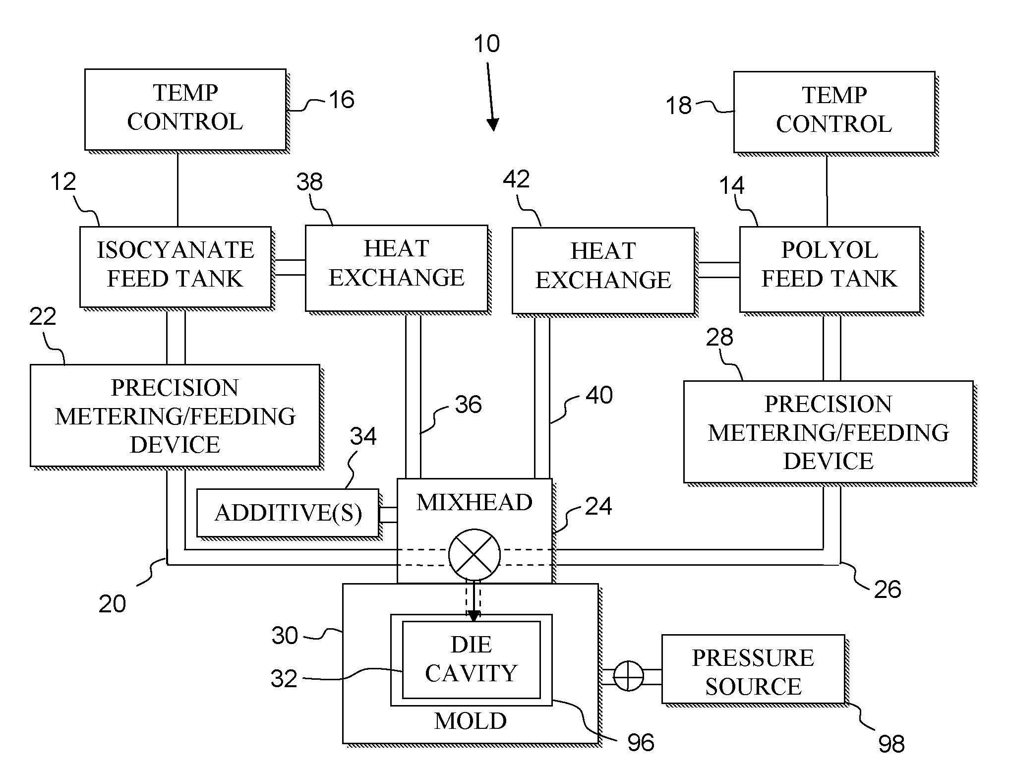
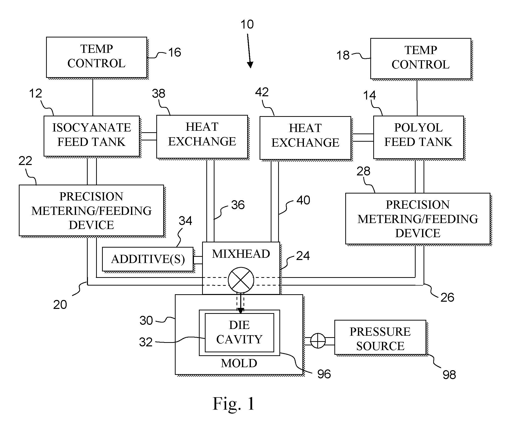
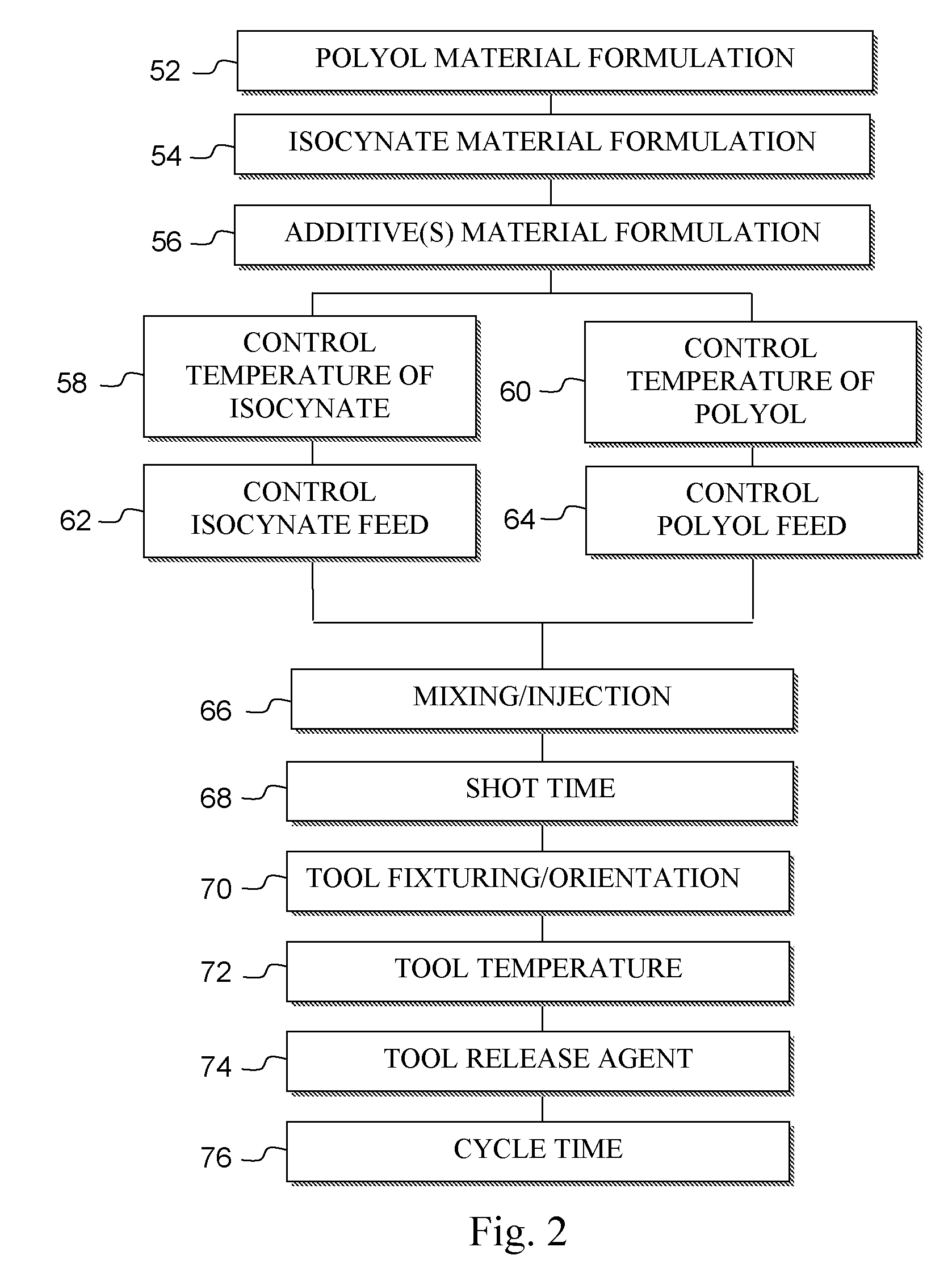
[0086]For purposes of illustration and not limitation, the following Example is offered. A RIM polyurethane foam pattern comprising isocyanate, polyol and additives, e.g., as described with reference to FIGS. 1-4 above, was molded in a one step operation in a RIM mold to have a shape of a medical hip implant. The pattern was made using the RIM parameters of 1800 psi mix pressure, 30 lbs / min flow rate, a 0.2 second shot time and mold temperature of 130 degrees Fahrenheit (approximately 54 degrees Celsius). A mold release agent was used to facilitate the release of the foam pattern from the RIM mold. The molded pattern had an aggregate density of about 8 lbs / ft3. The pattern was invested in a ceramic shell mold using “lost wax” process techniques such that the shell mold had a wall thickness generally up to 0.5 inches thick. The mold / pattern then was heated to 1900 degrees Fahrenheit (approximately 1038 degrees Celsius) in a furnace for a time of 120 minutes to burnout the pattern wit...


PUM

PropertyMeasurementUnit
densityaaaaaaaaaa
temperatureaaaaaaaaaa
pressureaaaaaaaaaa

Abstract

A foam material comprises a liquid polymer and a liquid isocyanate which is mixed to make a solution that is poured, injected or otherwise deposited into a corresponding mold. A reaction from the mixture of the liquid polymer and liquid isocyanate inside the mold forms a thermally collapsible foam structure having a shape that corresponds to the inside surface configuration of the mold and a skin that is continuous and unbroken. Once the reaction is complete, the foam pattern is removed from the mold and may be used as a pattern in any number of conventional casting processes.

Description

CROSS REFERENCE TO RELATED APPLICATIONS[0001]This application claims the benefit of U.S. Provisional Patent Application Ser. No. 60 / 947,941, filed Jul. 3, 2007, the disclosure of which is hereby incorporated by reference.STATEMENT REGARDING FEDERALLY SPONSORED RESEARCH OR DEVELOPMENT[0002]This invention was made with government support under Contracts No. FA8650-05-M-5304 and No. FA8650-06-C-5300 awarded by U.S. Air Force and Contract No. DE-FC36-04GO14332 awarded by the Department of Energy. The Government has certain rights in this invention.BACKGROUND OF THE INVENTION[0003]The present invention relates to casting processes for the manufacture metal and alloy structures, and more particularly, to systems, methods and materials associated with casting using fugitive patterns.[0004]Investment casting, which is also commonly known as the lost wax process, is one of the oldest known techniques utilized for forming metal. In practice, a wax substance is patterned, such as by injecting ...

Claims


Application Information

Patent Timeline
Patent Type & Authority Applications(United States)
IPC IPC(8): B22C3/00B22C7/00
CPCB22C7/023B29C44/60B29C44/0407B22C9/04B33Y80/00
Inventor CHAUDHRY, ANIL R.DZUGAN, ROBERTHARRINGTON, RICHARD M.NEECE, FAURICE D.SINGH, NIPENDRA P.
Owner PCC STRUCTURALS
Why Eureka
Try Eureka