[0010]The object of the invention is to develop the generic heaters such that the above explained problems are avoided, and at the same time, the possible uses of known flow sensors which work according to the calorimetric measurement principle are enhanced.
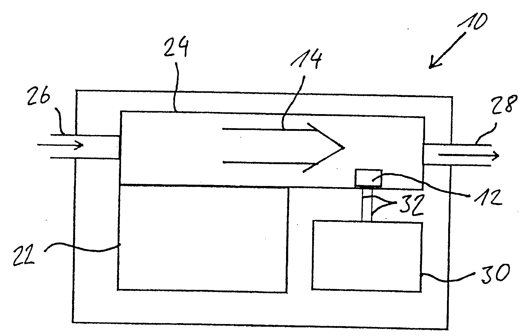
[0012]The heater in accordance with the invention is based on the generic prior art, but in instead, the means for determining the temperature and / or the means which operate as overheating protection comprises a flowmeter which works according to the calorimetric measurement principle. This approach is based on the finding that a component which is ordinarily used as a calorimetric flow sensor can be used as a temperature sensor, both as a temperature sensor for protection against overheating and also as a temperature sensor for measuring the temperature. Here, it is especially possible to use only a
single element for implementation of temperature detection and protection against overheating. This element preferably has a maximum of four and ideally two contacts; this will be explained in detailed. The total costs for the component which has been used in the past as protection against overheating can likewise be eliminated. Since it is then possible for the flow sensor which works according to the calorimetric measurement principle and which is used in accordance with the invention to evaluate the energy removal instead of a
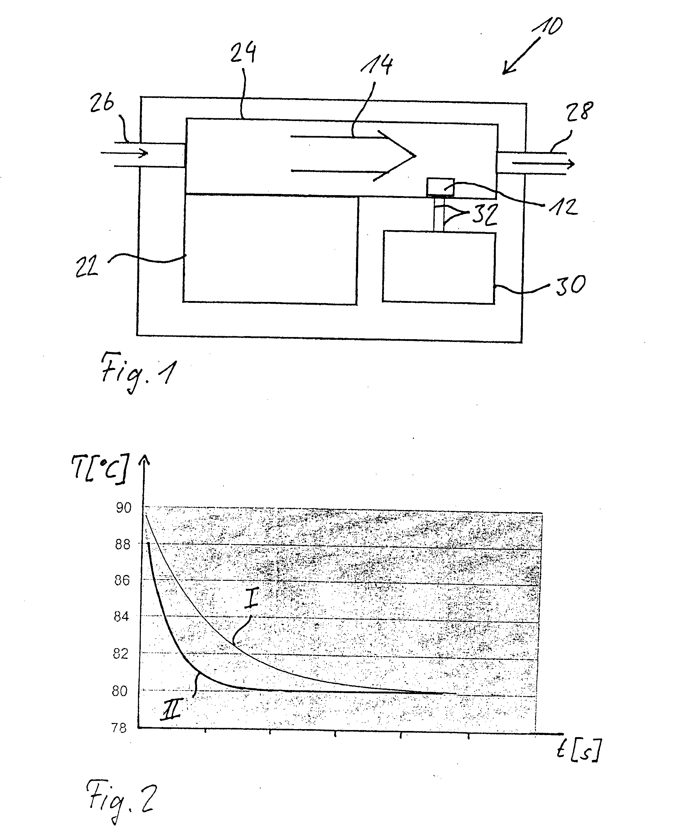
boundary temperature, critical states can be detected long before reaching the
boundary temperature. Thus, the
reaction rate of the system is greatly improved and the safety greatly enhanced. In particular, the initially mentioned problem of dry overheating is reliably managed by the approach in accordance with the invention, since the flow sensor recognizes the overly low energy removal long before the critical temperature is reached. In this way, the heater can withstand several dry overheatings without damage.
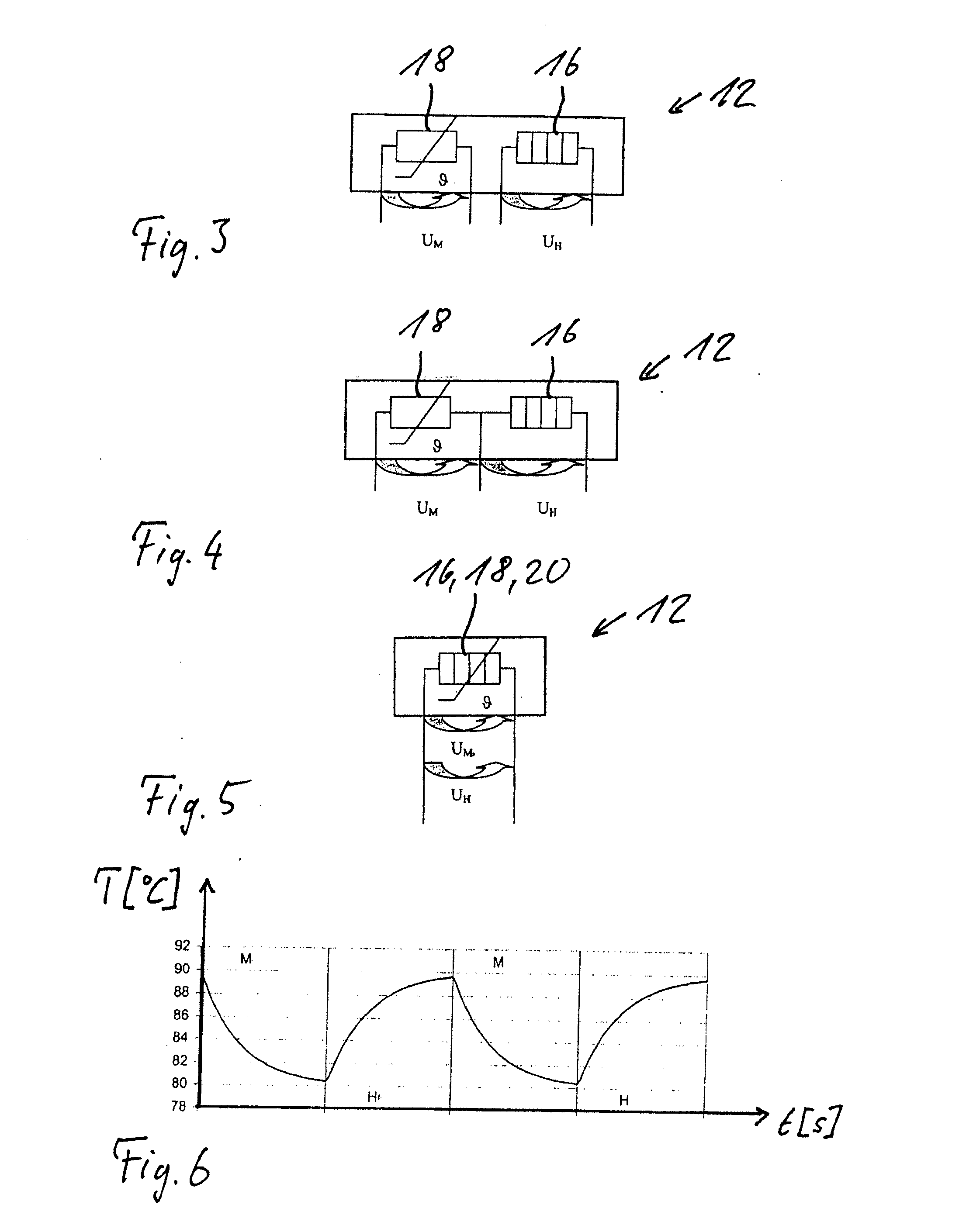
[0015]However, in the especially preferred embodiment of the heater in accordance with the invention, it is provided that the
heating element and the
temperature measurement means are formed by a component or group of components which operate in alternation as a
heating element and as a
temperature measurement means. For example, a suitable resistance element can be used in alternation as a heating
resistor and as a temperature-dependent measurement
resistor, so that the sensor need have only two contacts; this makes the sensor especially economical. Even if the design with only one element is especially economical, in systems for which increased safety is required, it can be feasible to use at least one other redundant system in addition to the checking of short circuits, interruption, operation and plausibility which preferably takes place. Therefore, in this case, an embodiment with two resistance elements which are used as a heating means and a
temperature measurement means is a good idea. It is assumed that the two resistors have temperature dependencies with characteristics which are known. Thus, it is possible in a
steady state to deduce the ambient temperature by measuring the resistance value on one
resistor, and from this ambient temperature to determine which resistance value the second resistor would have. If the deviation of this
set point relative to the actual value is outside of the tolerable range, there is an error in the sensor which, on the
software side, should lead to
initiation of the corresponding measures. Such measures can include, for example, faulty
interlocking of the vehicle
heating system. It is advantageous if the rated values, and optionally, the characteristics of the two resistors differ so that changes of properties, i.e., especially parasitic resistances, drifting and material changes, act differently on the measured values with reference to the standard characteristics. The check can be repeated cyclically and as often as desired between the normal working cycles of the sensor, therefore, also during burner operation of the vehicle
heating system.

