Abnormal condition detection apparatus

a technology of condition detection and abnormal condition, applied in the direction of instruments, material analysis, transportation and packaging, etc., can solve the problems of increased amount of data requiring a higher communication speed, required or desired amount of data not being transmitted within a predetermined time, and affecting the quality of communication, so as to reduce the amount of data to be transmitted and reduce the manufacturing cost

Active Publication Date: 2009-01-08
YAZAKI CORP
View PDF8 Cites 18 Cited by
  • Summary
  • Abstract
  • Description
  • Claims
  • Application Information

AI Technical Summary

Benefits of technology

[0014]In view of the foregoing background, an object of the present invention is to provide an abnormal condition detection apparatus that can transmit signals indicative of different types of the abnormal conditions from a plurality of abnormal condition detection units to a control unit while ensuring reduced amount of data to be transmitted and reduced manufacturing cost.
[0018]A waveform of the result signal can represent the different types of the abnormal conditions in a predetermined sequence in such a manner that the result signals as defined above shares only one combination of the high and low signal levels indicating the presence and the absence of the different types of the abnormal conditions. Thus, the results of detection of the abnormal conditions of more than one type can be sent to the control unit without providing an AND circuit or an OR circuit. Also, since the result signal is driven low when an abnormal condition has been detected, a low-level signal on which the result signals are superimposed can be output on the main line when any one of the result signals is driven low to indicate the presence of the abnormal condition, without providing logic gates such as the AND circuit and the OR circuit on the communication line. Thus, the amount of data to be transmitted can be reduced when compared with transmission of all the result signals in the sequential manner.

Problems solved by technology

Such conventional data transmission methodology has a drawback of degraded quality of communications, for increased amount of data requires a higher communication speed.
When the communications are made with a lower communication speed, required or desired amount of data may fail to be transmitted within a predetermined time.
Such solution is not very cost effective.

Method used


Image

  • Abnormal condition detection apparatus
  • Abnormal condition detection apparatus
  • Abnormal condition detection apparatus

Examples


Embodiment Construction

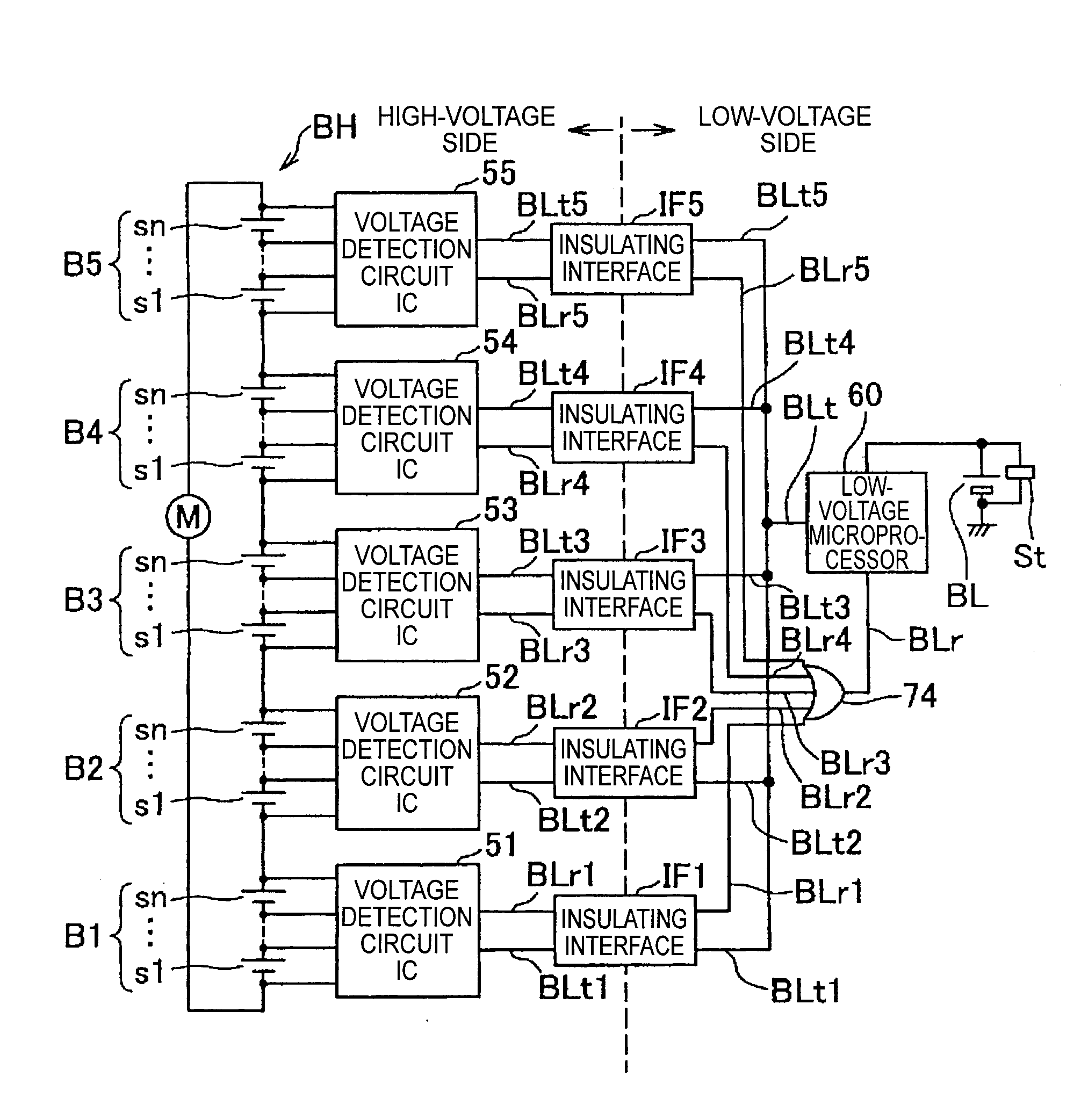
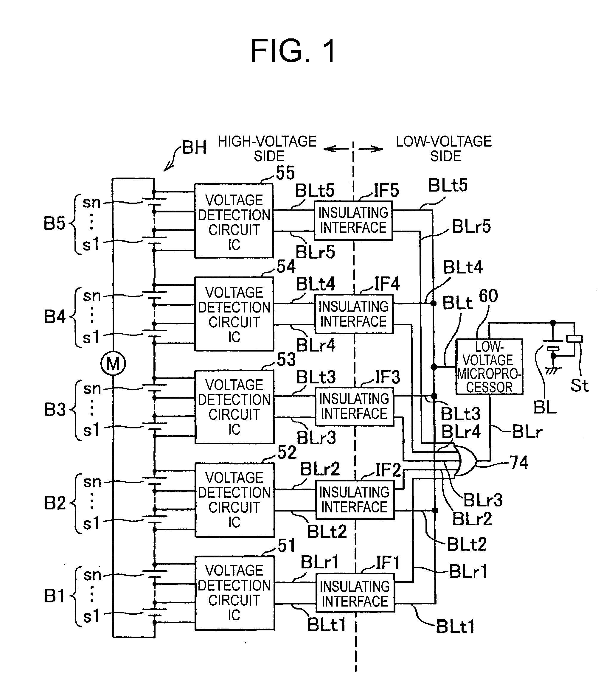
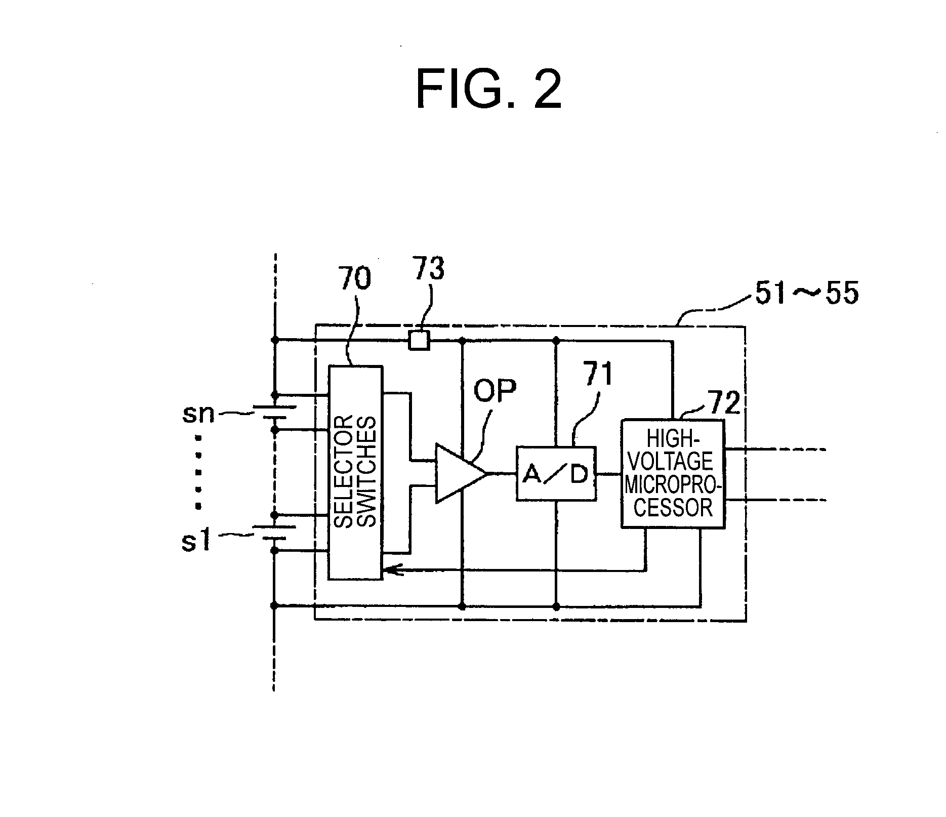
[0031]FIG. 1 illustrates a battery monitoring device incorporating an abnormal condition detection apparatus in accordance with one embodiment of the present invention.

[0032]A low-voltage battery indicated by a reference sign “BL” in FIG. 1 may be a single secondary cell. The low-voltage battery BL serves as a power source for a starter St used to start an engine. Components such as an alternator (not shown) are connected as a battery charger to positive and negative terminals of the low-voltage battery BL.

[0033]A high-voltage battery indicated by a reference sign “BH” in FIG. 1 is a battery pack of the present invention. The high-voltage battery BH serves as a power source for an electric motor M of an HEV having the engine and the electric motor M as its driving sources. The electric motor M is connected as a load to positive and negative terminals of the high-voltage battery BH. Components such as an alternator (not shown) are connected as a battery charger to the positive and ne...


PUM


Abstract

A plurality of result signals are driven low when abnormal condition is detected and driven high when no abnormal condition is detected. Presence and absence of the abnormal conditions of different types are indicated in a predetermined sequence by high and low signal levels of the result signals. The voltage detecting circuits simultaneously output the result signals on corresponding branching lines connected to a main line of a communication line. An OR gate outputs a result signal on which the result signals output by the voltage detecting circuits are superimposed. When at least one of the result signals of the voltage detecting circuits is at a level indicative of the presence of the abnormal condition, the OR gate outputs on the main line the result signal having the level indicative of the abnormal condition.

Description

DESCRIPTION OF THE RELATED ART[0001]1. Field of the Invention[0002]This invention relates to an abnormal condition detection apparatus, and, in particular, an abnormal condition detection apparatus that detects an abnormal condition on a battery-pack-block basis for a battery pack with unit cells composed of a secondary cell.[0003]2. Background of the Invention[0004]A hybrid electric vehicle (HEV) with an engine and an electric motor has two batteries, i.e., a low-voltage battery of about 12 volts for starting the engine and a high-voltage battery for driving the electric motor. The high-voltage battery is provided with unit cells that are connected in series, such as nickel-metal hydride and lithium secondary cells.[0005]The high-voltage battery, which is the battery pack as explained above, has battery blocks, each of which has a voltage detecting circuit. The voltage detecting circuit detects a voltage across the unit cells, and a result of detection is transmitted to a low-volta...

Claims


Application Information

Patent Timeline
Patent Type & Authority Applications(United States)
IPC IPC(8): G01R31/36H02J7/00H02J7/02
CPCG01R31/3658G01R19/16542G01R31/396
Inventor OKAMOTO, HAJIMESEKIZAKI, MASASHI
Owner YAZAKI CORP
Why Eureka
Try Eureka