Separate Support Structure for Loudspeaker Diaphragm

a support structure and loudspeaker technology, applied in the direction of transducer details, loudspeaker diaphragm shape, electrical transducers, etc., can solve the problems of difficult to solve reliability and service life problems, difficult to achieve the great breakthrough in technical performance of maturated products characteristic of integral support structures, etc., to achieve the effect of reducing the vibrating mass

Active Publication Date: 2009-01-08
DING YI
View PDF25 Cites 12 Cited by
  • Summary
  • Abstract
  • Description
  • Claims
  • Application Information

AI Technical Summary

Benefits of technology

[0012]In addition, compared with the integral support structure, for the cone and dome loudspeaker the separate support structure according to the invention eliminates the fold-ring to reduce the vibrating mass, which is particularly important for playing high frequency signal. Furthermore when the support structure of the present invention is applied to the ribbon loudspeaker and the planar-film loudspeaker, it may overcome the deficiency of the insufficient elastic deformation of the diaphragm material itself.

Problems solved by technology

However, the maturated product which is characteristic of the integral support structure is difficult to make a great breakthrough in the technical performance with the state of the art, in particular in the high-pitch and super-high-pitch field.
Although this loudspeaker is an excellent high-pitch unit, the corrugated aluminum ribbon diaphragm is susceptible to slack when it is operated by an electromagnetic force in long term and other strong external force.
The diaphragm may become elongated and offset the center area of the magnetic clearance so as to generate distortion at work, the problem concerning the reliability and service life is hard to be resolved over a long time of period.
Recently a compound diaphragm of polyimide and aluminum foil has been used in the ribbon loudspeaker, and in a head of the ribbon diaphragm a metal spring in a waveform as a transition section of the support-structural member serves as the integral support structure, which improves the reliability and service life of the ribbon diaphragm in a certain extent, however the problem of stress concentration at a interface between the strip compound diaphragm and the waveform supporting-structural member is still difficult to be resolved since it is not perfect technically.
This means that the elasticity of the supporting ring of the diaphragm cannot sufficiently satisfy the requirement of the diaphragm vibration.
As a result of the permanent deformation the diaphragm offsets the normal work area and produces distortion.
This kind structure has a certain limitation in technology.

Method used


Image

  • Separate Support Structure for Loudspeaker Diaphragm
  • Separate Support Structure for Loudspeaker Diaphragm
  • Separate Support Structure for Loudspeaker Diaphragm

Examples


first embodiment

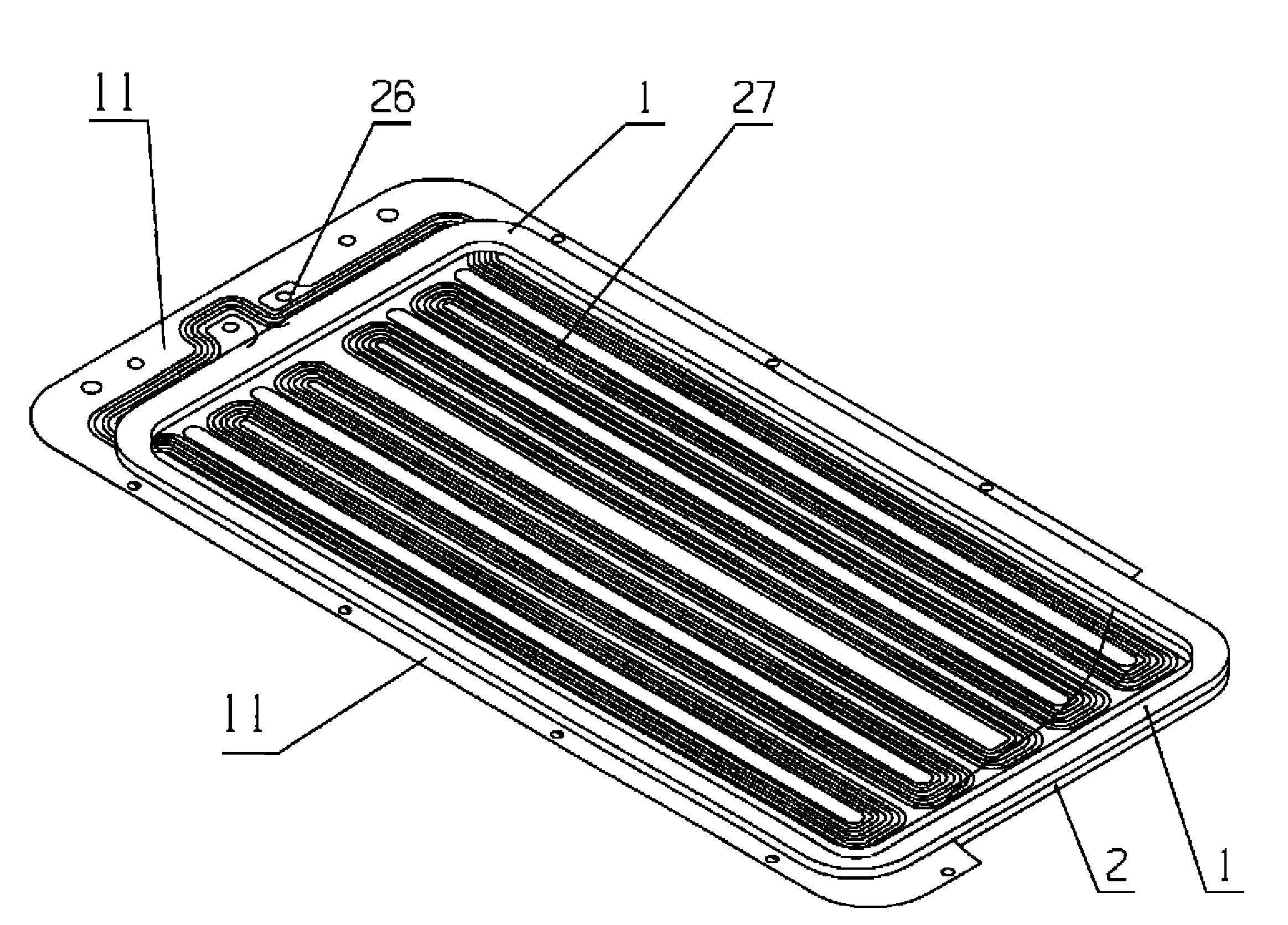
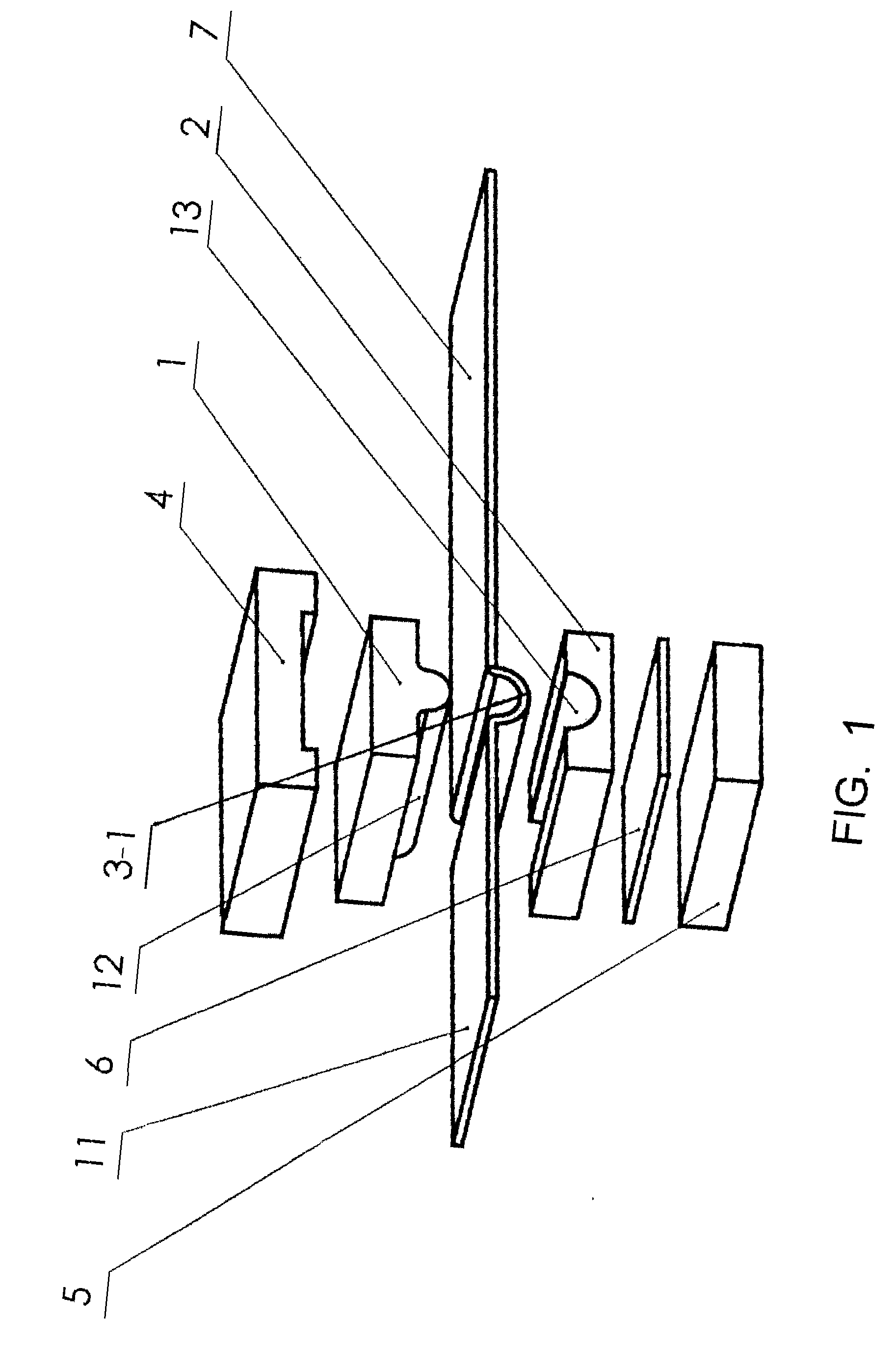
[0051]In FIG. 1, there is shown a separate support structure for the loudspeaker diaphragm according to the invention, and this kind of support structure is used for retaining the positioning of the diaphragm and keeping the vibration of the loudspeaker diaphragm. The support structure includes a first curved-surface elastic body 1, a second curved-surface elastic body 2 and a supported portion 3-1 of the loudspeaker diaphragm. In this embodiment, the first curved-surface elastic body 1 has a first engaged face 12 with a convex curved-surface shape, and the second curved-surface elastic body 2 has a second engaged face 13 with a concave curved-surface shape which is complementary to the curved-surface shape of the first curved-surface elastic body. The first engaged face 12 of the first curved-surface elastic body and the second engaged face 13 of the second curved-surface elastic body engage oppositely from both sides of the supported portion 3-1 of the loudspeaker diaphragm 7 and ...

second embodiment

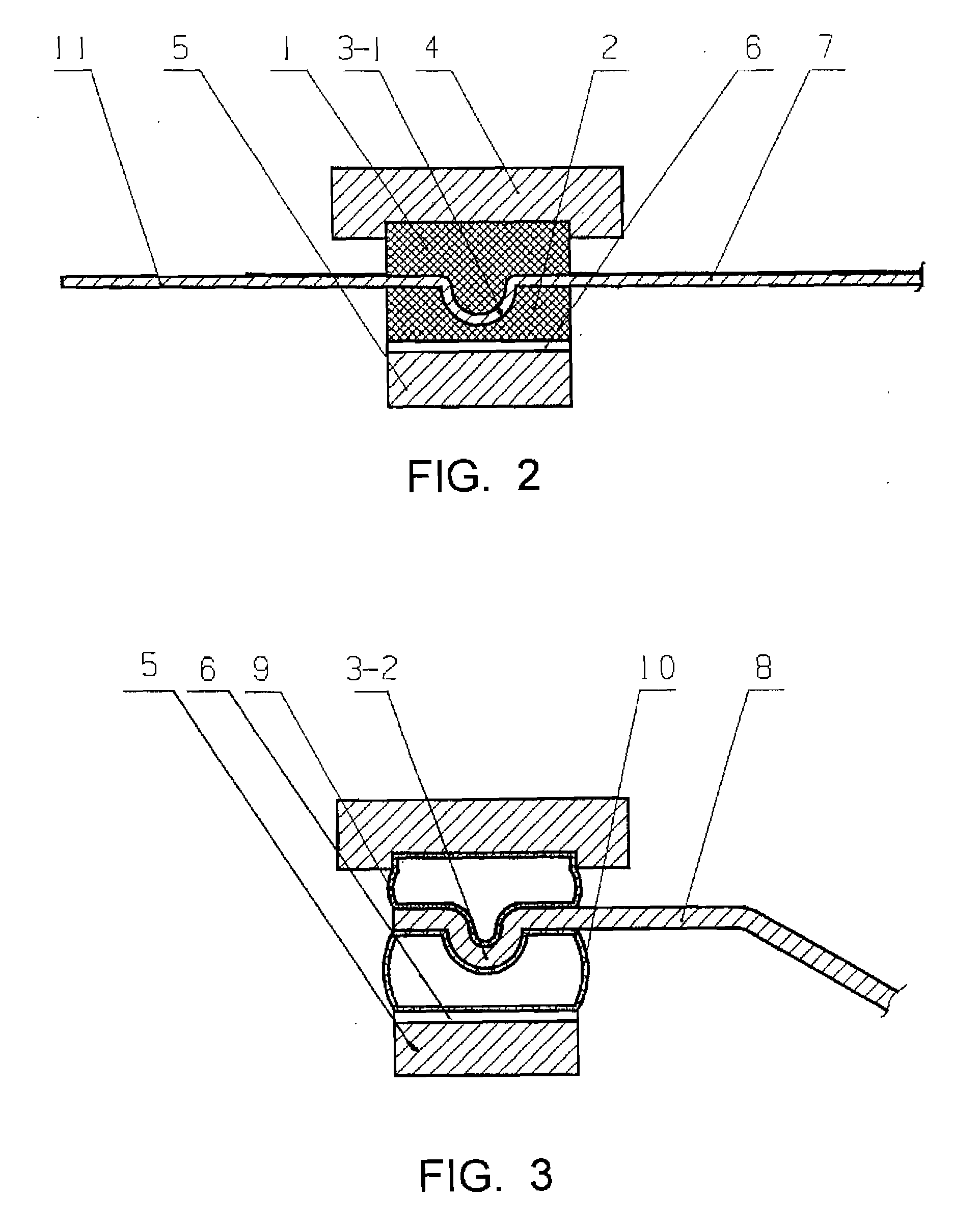
[0056]FIG. 3 shows the support structure of the loudspeaker diaphragm according to the present invention. Similarly, the structure shown in FIG. 3 is also a separate support structure for the loudspeaker diaphragm. In comparison with the structure shown in FIG. 2, the loudspeaker diaphragm in FIG. 3 is a rigid diaphragm 8, which has a rigid supported portion 3-2. The first curved-surface elastic body 9 and the second curved-surface elastic body 10 are both hollow elastic pieces, which are made of resilient material of macromolecule. Similarly, the supported portion 3-2 of the rigid diaphragm 8 is sandwiched between the first engaged face of the first curved-surface elastic body 9 and the second engaged face of the second curved-surface elastic body 10 so that it is able to support and retain the loudspeaker diaphragm. As shown in the figure, the first hollow curved-surface elastic body 9 has a convex curved-surface shape and the second hollow curved-surface elastic body 10 has a con...

third embodiment

[0060]FIG. 4 shows a support structure of metallic thin plate for a diaphragm according to the present invention. The support structure includes a first metallic curved-surface elastic body 16 having a first engaged face and a second metallic curved-surface elastic body 17 having a second engaged face, the engaged faces of the two metallic curved-surface elastic bodies 16 and 17 have S-shape curved matching surfaces, a diaphragm is sandwiched between the two engaged faces which are complementarily matched together. It should be noted that the separate support structure is formed of the supported portion and the first and second elastic bodies 16, 17, that is, there is no connection means, such as an adhesive, between them.

[0061]The first and second metallic curved-surface elastic bodies have fixation sections 14 and 15 for the elastic bodies, respectively, so that they may be connected to the loudspeaker body by means of welding, a fastener, or an insertion slot. In the illustrated ...


PUM


Abstract

A support structure for supporting and protecting the diaphragm of loudspeaker includes a first elastomer which has a first interface with a camber shape, a second elastomer which has a second interface with a complemental shape of the first interface, the first elastomer and the second elastomer combine together from both sides of the support part of the loudspeaker diaphragm. The separate support structure in the present invention is fit for many kinds of loudspeakers and propitious to increase the technical characteristics of loudspeakers.

Description

TECHNICAL FIELD[0001]The invention relates to the field of electroacoustical technology, more specially to a support structure for positioning of a diaphragm in a loudspeaker and keeping vibration of the diaphragm. In particular, the present invention relates to a separate kind of support structure for the diaphragm.BACKGROUND OF THE INVENTION[0002]Diaphragms used in most of the cone and dome loudspeaker in the present market are supported by means of a fold-ring (some including a centering tab), the fold-ring supports the diaphragm so that the diaphragm vibrates under the action of a electroacoustical driving force to output the sound, and the fold-ring and the diaphragm form an integral structure. Some fold-rings and diaphragms are made of same material, both being an integral structure; some fold-rings and diaphragms are made of different materials, both also being an integral structure by bonder means.[0003]A lot of efforts are made on the diaphragm, fold-ring and material, as w...

Claims


Application Information

Patent Timeline
Patent Type & Authority Applications(United States)
IPC IPC(8): H04R7/20
CPCH04R7/20H04R2307/207H04R2307/204
Inventor DING, YI
Owner DING YI
Why Eureka
Try Eureka