Automatic vending machine and serial bus system suitable to the same
a serial bus and vending machine technology, applied in the direction of digital transmission, data switching network, instruments, etc., can solve the problems of complex connectors and wiring, difficult addition of modules, and difficult maintenance performance, so as to improve maintenance performance and ensure the effect of reset operation
- Summary
- Abstract
- Description
- Claims
- Application Information
AI Technical Summary
Benefits of technology
Problems solved by technology
Method used
Image
Examples
first embodiment
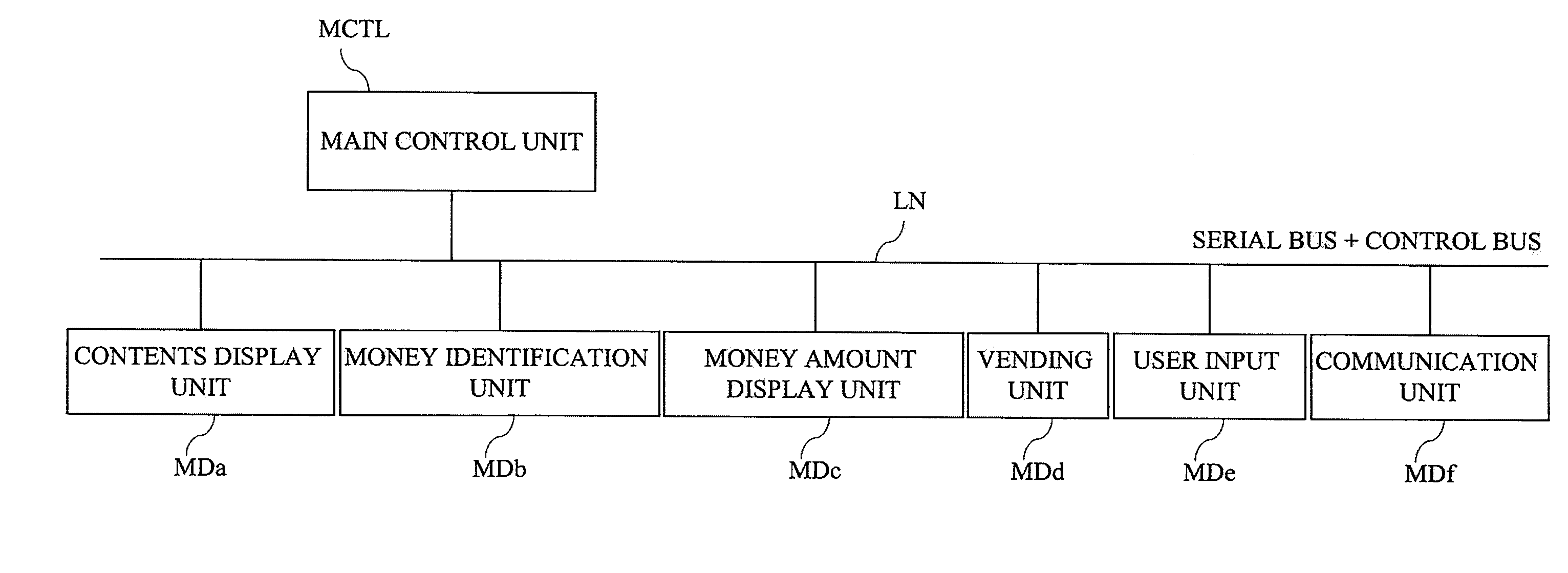
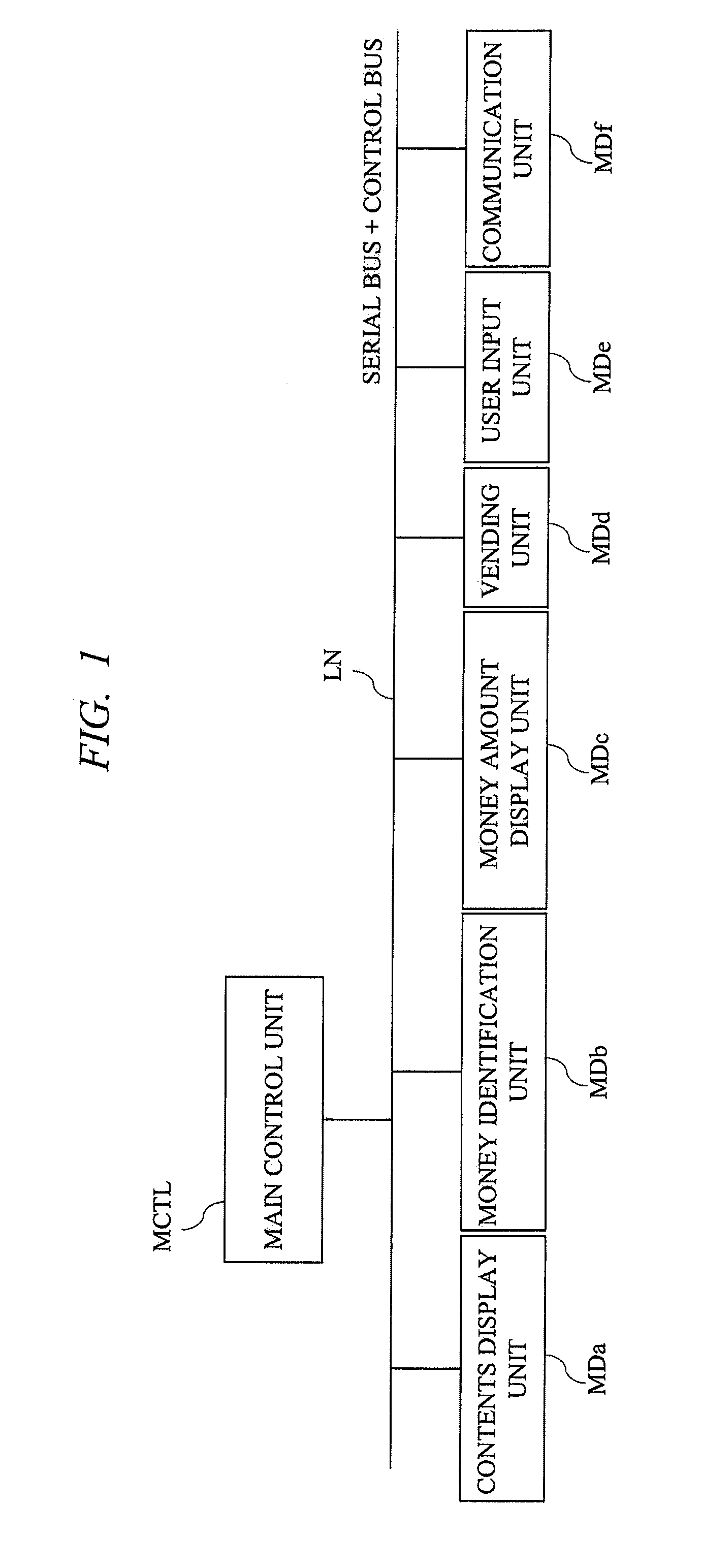
[0040]FIG. 1 is a block diagram showing an example of a configuration of an automatic vending machine according to a first embodiment of the present invention. The automatic vending machine shown in FIG. 1 has a configuration in which a main control unit MCTL and a plurality of peripheral modules MD are connected on a communication line LN. And, it is a feature that the peripheral modules MD connected to the LN includes, for example, a contents display unit MDa and a communication unit MDf in addition to a money identifying unit MDb, a money amount display unit MDc, a vending unit MDd, a user input unit MDe, etc.
[0041]The money identifying unit MDb has a function of identifying the money inserted into the automatic vending machine, and the money amount display unit MDc has a function of displaying the identified money. The user input unit MDe has a function of controlling user interfaces typified by buttons of the automatic vending machine, and the vending unit MDd has a function of...
second embodiment
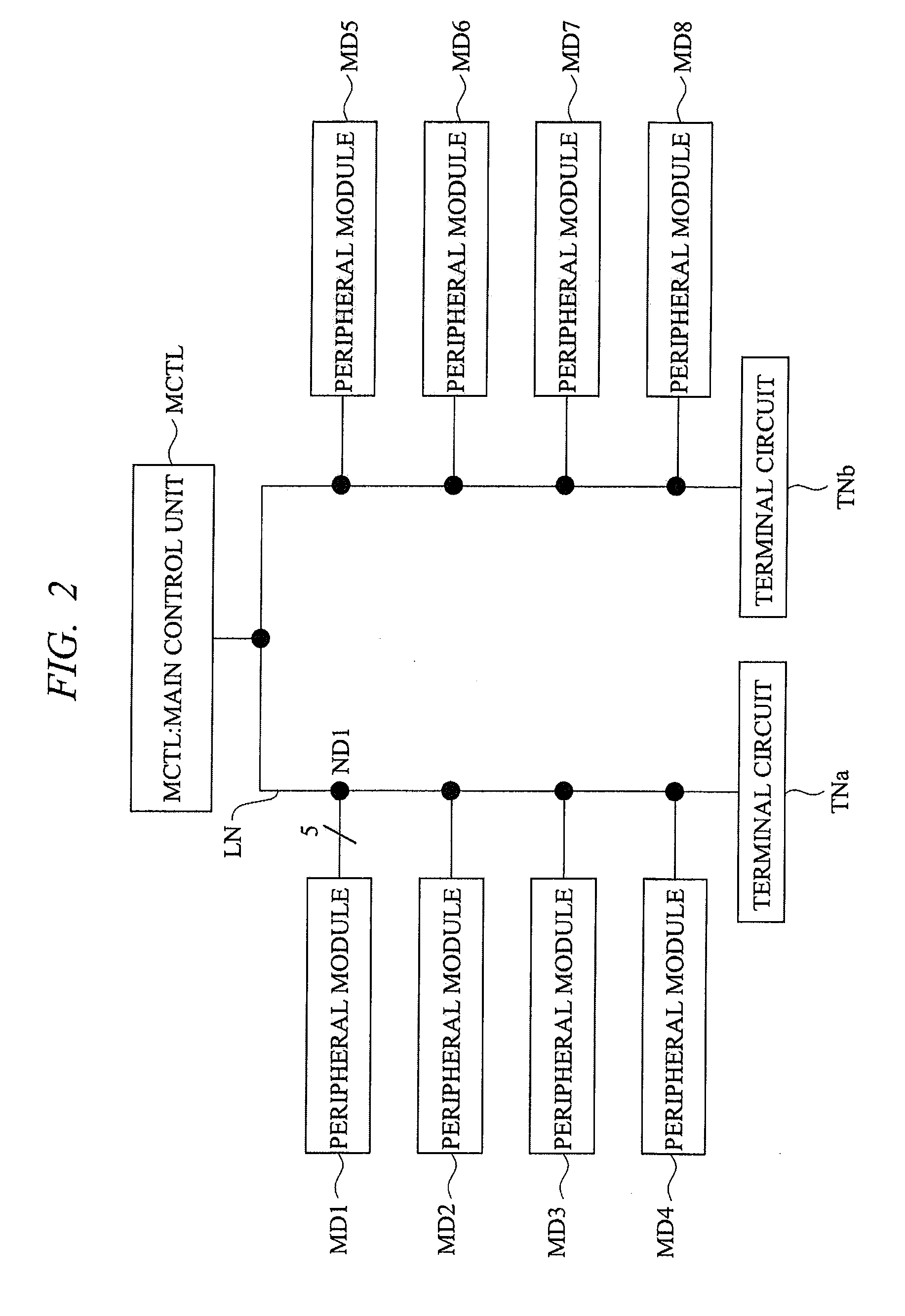
[0072]In a second embodiment, a configuration example which is a modification of the wiring topology of FIG. 2 described in the first embodiment will be described. In addition, a detailed configuration example including the internal circuits of the main control unit and the peripheral module will be also described.
[0073]FIG. 11 is a block diagram showing an example of a configuration of a serial bus system according to the second embodiment of the present invention. As with FIG. 2, the serial bus system shown in FIG. 11 has a configuration in which a main control unit MCTL_W and a plurality of peripheral modules MD_WL to MD_W8 are electrically connected on the communication line LN, and both ends of the communication line LN are provided with the terminal circuits TNa and TNb.
[0074]The difference from FIG. 2 is the wiring topology in which the communication line LN is once extended into the interior of each of the peripheral modules MD_W, and the part extended from there to the outs...
third embodiment
[0086]In a third embodiment, an example in which an automatic vending machine is composed by applying the wiring topology of FIG. 11 described in the second embodiment will be described. FIG. 14 is a block diagram showing an example of a configuration of the automatic vending machine according to the third embodiment of the present invention.
[0087]The automatic vending machine shown in FIG. 14 has the configuration in which, as with FIG. 11, a main control unit MCTL_W and a plurality of peripheral modules MD_Wa to MD_Wj are electrically connected on the communication line LN, and the terminal circuits TNa and TNb are connected at both ends of the communication line LN. MD_Wa is a wireless modem and has a function of carrying out wireless transmission / reception of data with outside via an antenna ANT. MD_Wb is a money amount display unit and has the function of displaying the money inserted by a user.
[0088]MD_Wc is a so-called coin mechanism and has the function of identifying the co...
PUM
 Abstract
Description
Claims
Application Information
 - R&D
- Intellectual Property
- Life Sciences
- Materials
- Tech Scout
- Unparalleled Data Quality
- Higher Quality Content
- 60% Fewer Hallucinations
Browse by: Latest US Patents, China's latest patents, Technical Efficacy Thesaurus, Application Domain, Technology Topic, Popular Technical Reports.
© 2025 PatSnap. All rights reserved.Legal|Privacy policy|Modern Slavery Act Transparency Statement|Sitemap|About US| Contact US: help@patsnap.com


