Check patentability & draft patents in minutes with Patsnap Eureka AI!

Input apparatus and input method

a technology of input apparatus and input method, which is applied in the direction of pulse technique, instruments, specific gravity measurement, etc., can solve the problems of reducing the thickness of the operating portion, affecting the strength of the metal plate , reducing the thickness of the portable terminal, so as to prevent the occurrence of contact failure, reduce the thickness, and reduce the thickness of the input apparatus

Inactive Publication Date: 2009-01-15
LENOVO INNOVATIONS LTD HONG KONG
View PDF6 Cites 11 Cited by
  • Summary
  • Abstract
  • Description
  • Claims
  • Application Information

AI Technical Summary

Benefits of technology

The present invention provides an input apparatus and method that enable a reduction in thickness and prevention of contact failure. The apparatus includes a substrate on which a signal line has been formed, and an insulating sheet disposed facing the substrate and having information, which represents a plurality of operating positions. The apparatus also includes reflected-wave detecting means for detecting a reflected wave of the signal that has been output by the signal transmitting means, and computing means for discriminating an operating position at which an operation has been performed, based upon the reflected wave detected by the reflected-wave detecting means. The invention also provides an input method using the apparatus and a storage means correlating the result of time domain reflectometry and entered instructions. The technical effects of the invention include a reduction in thickness of the key portion and prevention of contact failure.

Problems solved by technology

As a consequence, it is difficult to reduce the thickness of the operating portion.
The result is that a reduction in the thickness of the portable terminal is impeded.
Further, when the metal plate 9 is reduced in thickness in order to reduce the thickness of the key portion, a problem which arises is that the strength of the metal plate 9 declines, leading to the danger of destruction.
Furthermore, since the piezoelectric element is provided on one surface of the substrate in the switch described in Patent Document 1, it is difficult to achieve a reduction in thickness.

Method used


Image

  • Input apparatus and input method
  • Input apparatus and input method
  • Input apparatus and input method

Examples


Embodiment Construction

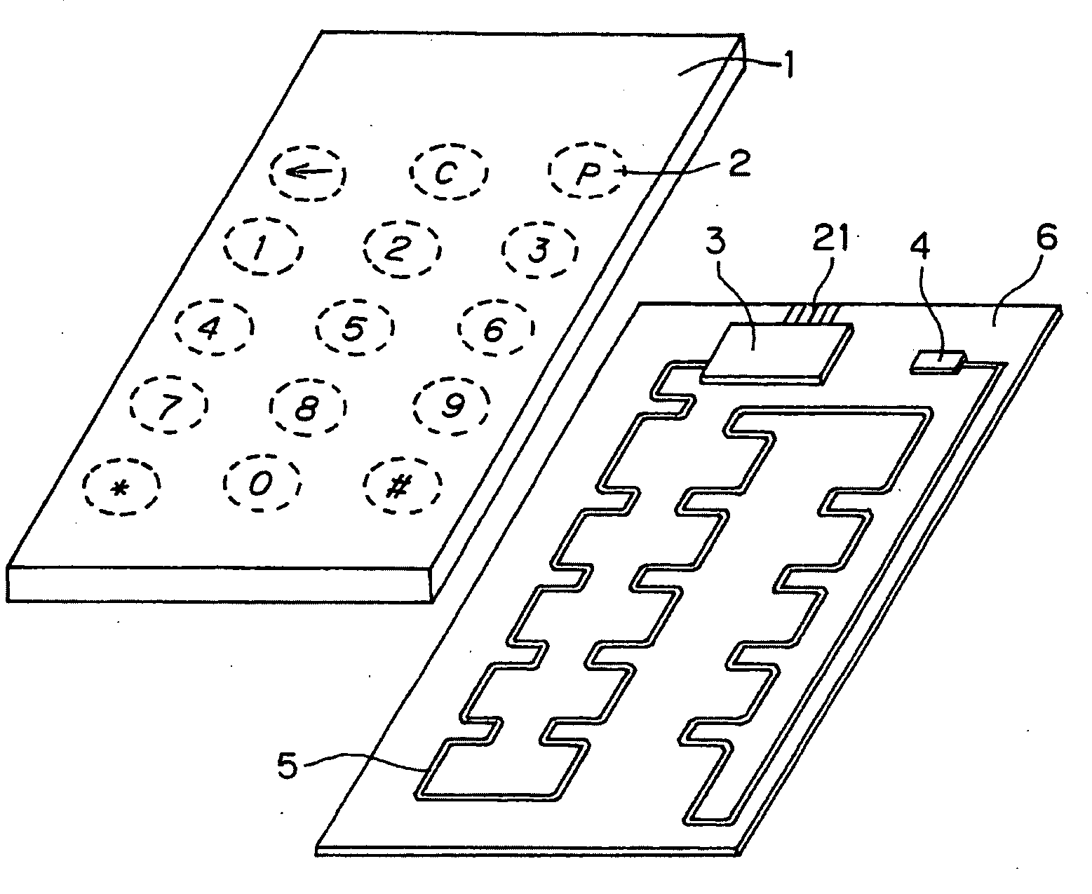
[0037]Exemplary embodiments of the present invention will be described with reference to the drawings. FIG. 1 is a perspective view illustrating an example of the configuration of a key input apparatus (input apparatus) according to an exemplary embodiment of the present invention.

[0038]The key input apparatus shown in FIG. 1 includes an elastic key sheet (insulating sheet) 1, the main ingredient of which is silicone rubber or the like, and a substrate 6 on which a coplanar line 5 has been formed.

[0039]In a case where the key sheet 1 is applied to numeric keys, numerals and the like are printed on one surface of the key sheet 1 and recesses of a conical or cylindrical shape are provided at portions on the other surface that correspond to the numerals, etc., printed on the first-mentioned surface. In other words, the positions of the recesses provided in one surface of the key sheet 1 correspond to positions 2 of keys of the numerals, etc., printed on the key sheet 1.

[0040]A terminat...


PUM

PropertyMeasurementUnit
frequencyaaaaaaaaaa
distanceaaaaaaaaaa
frequencyaaaaaaaaaa

Abstract

Disclosed is an input apparatus including a coplanar line formed on the surface of a substrate so as to pass through the vicinity of a position at which a user performs an operation, terminating resistor placed at one end of the coplanar line and a microcomputer module at the other end. The microcomputer module has a signal transmitter for outputting a signal to the coplanar line. When the user operates a key, the impedance of the coplanar line changes and a reflected wave is produced. A signal detector in the microcomputer module detects the reflected wave and outputs received-signal strength information, which indicates the strength of the signal included in the reflected wave, to a computing unit. Based upon the received-signal strength information and strength of the signal that has been output by the signal transmitter, the computing unit in the microcomputer module discriminates the key that has been operated and specifies the entered instruction.

Description

TECHNICAL FIELD[0001]This invention relates to a thin-type input apparatus and to an input method.BACKGROUND ART[0002]FIG. 11 is an explanatory view illustrating the configuration of a key portion at a conventional operating portion used in a portable terminal. A top view of the conventional key portion is illustrated in FIG. 11A, and a sectional view of the conventional key portion is illustrated in FIG. 11B.[0003]The key portion illustrated in FIG. 11 includes a flexible key sheet placed in electrical insulation relative to a substrate 6 and having a recess with respect to the substrate 6, and a metal plate 9 secured in the recess as by an adhesive sheet or the like.[0004]Further, as illustrated in FIG. 11B, the edge of the metal plate 9 is in contact with a pad face 7 formed on the substrate 6, and the central portion of the metal plate 9 is disposed so as to be displaceable in directions toward and away from the substrate 6. When the central portion of the metal plate 9 is press...

Claims


Application Information

Patent Timeline
Patent Type & Authority Applications(United States)
IPC IPC(8): G01N29/00
CPCG06F3/0202H03K17/96H01P5/04
Inventor YAMASAKI, SHUJI
Owner LENOVO INNOVATIONS LTD HONG KONG
Features
  • R&D
  • Intellectual Property
  • Life Sciences
  • Materials
  • Tech Scout
  • Unparalleled Data Quality
  • Higher Quality Content
  • 60% Fewer Hallucinations
Learn More