Dual crimped warp fabric for conveyor belt applications

a technology of crimping warp weave and conveyor belt, which is applied in the direction of turning machines, textiles and papermaking, synthetic resin layered products, etc., can solve the problems of reducing the total strength of the resulting belt, reducing the flexibility of the belt, and reducing the overall strength of the belt, so as to achieve high strength and high strength. , the effect of improving flexibility

Active Publication Date: 2009-01-15
FENNER DUNLOP AMERICAS
View PDF16 Cites 15 Cited by
  • Summary
  • Abstract
  • Description
  • Claims
  • Application Information

AI Technical Summary

Benefits of technology

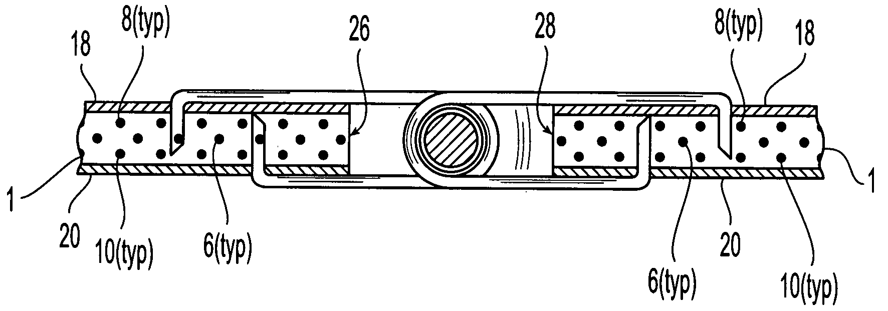
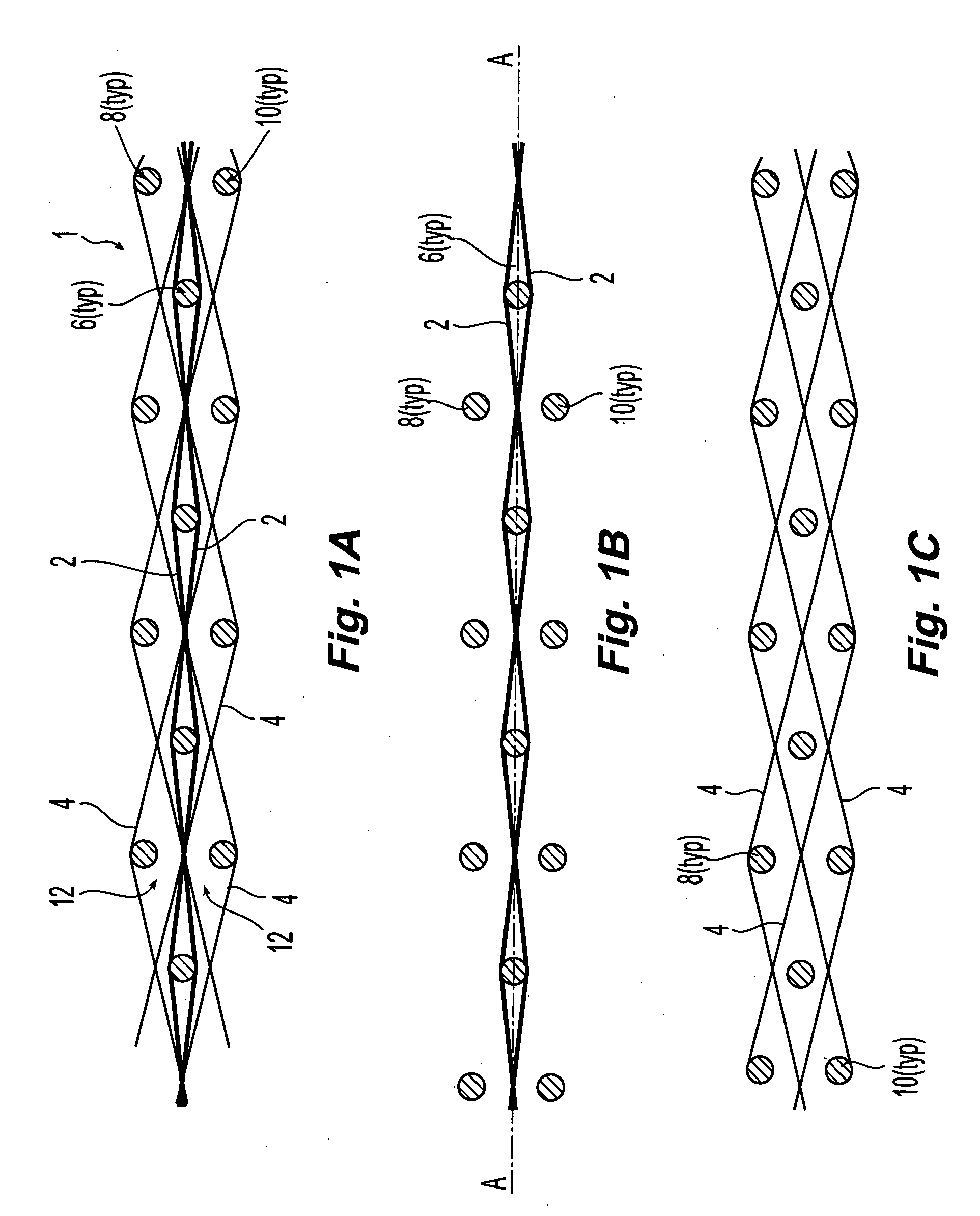
[0006]The disadvantages heretofore associated with the prior art are overcome by the inventive design for a conveyor belt having a fabric carcass comprising a dual crimped warp arrangement. The inventive design provides advantages including, enhanced flexibility with high strength, enabling the building of very high strength multiply carcasses.

Problems solved by technology

Since the tension members in these straight warp weaves do not intertwine with the wefts, they do not help to lock the wefts in place to resist weft pullout when tension is applied to the belt via the conveyor belt fastener lacings.
Further, although the un-crimped arrangement of the warps in straight warp weave designs provide the belt with an extremely high modulus of elasticity in the running direction (the resulting belt will therefore undergo minimal stretch even when subjected to the high tensile loads applied by the conveyor system pulleys), such high strength brings with it high stiffness.
This can be a problem where the belt is required to bend around the tight radius of a return-idler or tail-pulley.
Thus, to ensure that adequate flexibility, the total number of reinforcing fabric “plies” may be limited to only one or two, which disadvantageously limits the total strength of the resulting belt.

Method used


Image

  • Dual crimped warp fabric for conveyor belt applications
  • Dual crimped warp fabric for conveyor belt applications
  • Dual crimped warp fabric for conveyor belt applications

Examples


example 1

[0043]A fabric layer according to the invention was constructed in accordance with Tables I, II and III.

TABLE ITwistsMinimumSize# ofTwistperTensileYarn(Denier)PliesDirectionInch(lpf)CentralPolyester10009 (for aS1.8152tensiontotal ofwarps9000denier)BinderPolyester10003 (for aS2.550warpstotal of3000denier)WeftsNylon12608 (for aS1.8178total of10,080denier)

TABLE IICentralCentralTensionTensionBinderWarpWarpWarpBinderWeftWeftCountCrimpCountWarpCountCrimp(EPI)(%)(EPI)Crimp(PPI)(%)STD194.538.030.0122.0MIN18.73.537.427.511.51.5MAX19.35.538.633.512.52.5

TABLE IIIGauge (Inches)Weight (OPSY)STD0.14059.3MIN0.13357.8MAX0.14760.8

example 2

[0044]A fabric layer was manufactured in accordance with Table I, with the following additional characteristics:

TABLE IVWarpBinderFillingGaugeWarpBinderFilling%%%(In.)OpsyCountCountCountCrimpCrimpCrimp0.14060.819.53997.58.751.9

[0045]Natural rubber top and bottom covers having thicknesses of 207 mils and 116 mils, respectively, were applied to a single fabric layer that had previously been RFL treated. Results from testing are shown in Table V below. All testing was performed in accordance with ASTM D378, “Standard Test Methods for Rubber (Elastomeric) Belting, Flat Type.”

TABLE VPhysical CharacteristicResultsAverageTensile Strength, PIW (pounds4150, 4350, 39504150per inch width)Elongation at 330 lbs1.05Tensile Transverse, PIL2330, 24002365(pounds per inch length)Elongation at Break (%)25, 2525Fastener Pullout (PIW);1449Flexco Type F-190E(bolt / plate type fastener)Fastener Pullout (PIW);1660Flexco Type F-R5(hinged / rivet type fastener)Adhesion - Top (PIL)49Adhesion - Bottom (PIL)39Trans...


PUM

PropertyMeasurementUnit
lengthsaaaaaaaaaa
thicknessesaaaaaaaaaa

Abstract

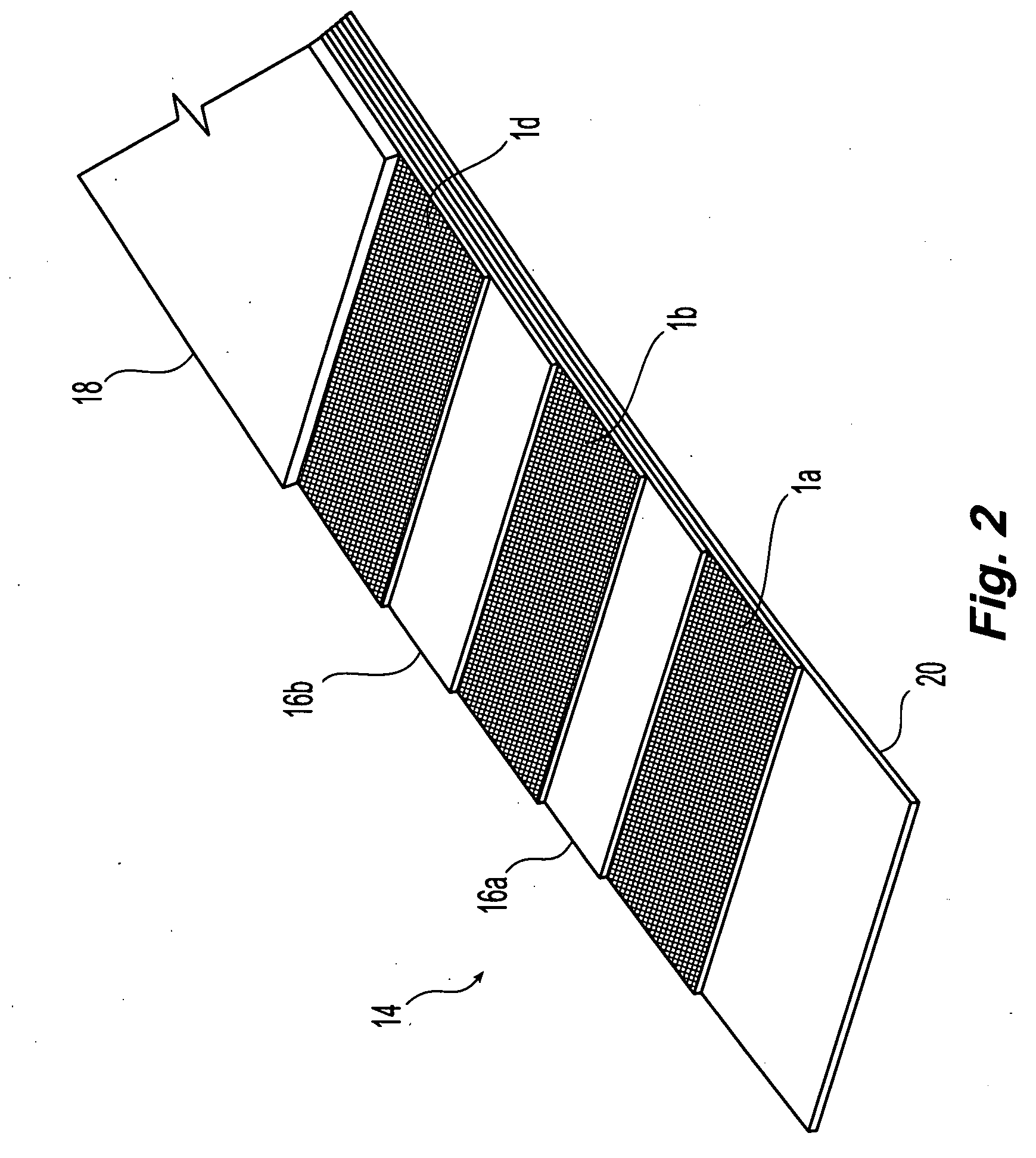
A conveyor belt reinforcing fabric weave is disclosed, having a plurality of center tension warps crimped about a plurality of middle wefts. Upper and lower wefts lie above and below the middle wefts. The upper and lower wefts are in opposition to each other and in non-opposition with the center wefts. Binder warps are interlaced above and below the central tension warps in alternating sequence, with at least one of the binder warps interlacing upper and lower wefts other than those interlaced by an adjacent binder warp. Interlacing of the middle wefts by the central tension warps locks the wefts in place, providing enhanced resistance to faster pullout. The lack of straight tension warps provides a highly flexible fabric that can be used in multi-ply applications. A conveyor belt incorporating one or more plies of the inventive fabric is disclosed, as is a method for manufacturing the belt.

Description

FIELD OF THE INVENTION[0001]The invention generally relates to an improved fabric for use in conveyor belt carcass applications, and more particularly to a design for a high strength fabric having a dual crimped warp weave for providing enhanced mechanical fastener holding and improved modulus control for conveyor belt carcasses.BACKGROUND[0002]Conveyor belts and conveyor systems are well known systems used for the transport of a variety of materials and products. Conveyor belts are designed and used in heavy materials transport such as coal mining and cement manufacturing operations, and in medium and light weight applications such as light materials handling operations, package handling and transport, and the like. For heavyweight applications, it is desirable to provide a belt with high strength, and also one that will resist damage due to impacts with the material being carried, such as where high volumes of hard, sharp or irregular-shaped product are loaded on the belt.[0003]Cu...

Claims


Application Information

Patent Timeline
Patent Type & Authority Applications(United States)
IPC IPC(8): D03D3/00
CPCB32B25/10B32B2433/02B65G2201/045D03D1/0094D03D3/04D03D11/00D03D15/00D03D15/0094D06M15/693D10B2101/06D10B2201/28D10B2211/02D10B2321/022D10B2331/02D10B2331/021D10B2331/04D10B2401/062D10B2401/063D10B2505/02B32B2260/021B32B2260/048B32B2307/50B65G15/34Y10T442/3008Y10T442/3317Y10T442/3854Y10T442/3228Y10T442/326Y10T442/2893Y10T442/3301Y10T442/2041Y10T442/3276Y10T442/3285Y10T442/273Y10T442/2861Y10T442/3195Y10T442/2738Y10T442/3179Y10T442/3016Y10T442/3211Y10T442/322Y10T442/3203Y10T442/2049D03D15/43D03D15/573D03D15/41D03D15/283
Inventor HAWKINS, JOHNNORMANTON, GEOFF
Owner FENNER DUNLOP AMERICAS
Why Eureka
Try Eureka