Anthracene Derivative, Material for Light Emitting Element, Light Emitting Element, Light Emitting Device, and Electronic Device

a technology of anthracene derivative and light emitting element, which is applied in the field of anthracene derivative, can solve the problems of difficult to realize a light emitting element and the light emitting element for blue with high reliability and excellent color purity has not been realized, etc., and achieves high color purity, high reliability and high light emitting element reliability.

Active Publication Date: 2009-01-15
SEMICON ENERGY LAB CO LTD
View PDF33 Cites 65 Cited by
  • Summary
  • Abstract
  • Description
  • Claims
  • Application Information

AI Technical Summary

Benefits of technology

[0044]Further, anthracene derivatives according to the invention is added into a layer including a material having larger band gap than the anthracene derivative according to the invention (hereinafter referred to as a host) to manufacture a light emitting element; thus, light emitted from the anthracene derivative according to the invention can be obtained. Accordingly, the anthracene derivative according to the invention also functions as a dopant. Hereupon, the anthracene derivative according to the invention has extremely large band gap. and emits light of having short wavelength. Thus, a light emitting element which can provide blue light emission with highly color purity can be manufactured.
[0045]Further, as to a light emitting element in which an anthracene derivative having a diarylamine structure according to the invention is used as a dopant, and among anthracene derivatives proposed in the present invention, particularly an anthracene derivative which does not have a diarylamine structure is used as a host, highly electrochemically stable anthracene derivatives of the invention are used for both the host and the dopant. Therefore, a highly reliable light emitting element can be obtained.
[0046]Further, using a light emitting material containing the above-described anthracene deriv

Problems solved by technology

However, there is a problem in a full-color light emitting device that a light emitting element with excellent color purity can not always be manufactured easily.
This is because it is difficult to realize a light emitting element with high reliability and excellent color purity, although light emitting elements for red, blue and green with

Method used


Image

  • Anthracene Derivative, Material for Light Emitting Element, Light Emitting Element, Light Emitting Device, and Electronic Device
  • Anthracene Derivative, Material for Light Emitting Element, Light Emitting Element, Light Emitting Device, and Electronic Device
  • Anthracene Derivative, Material for Light Emitting Element, Light Emitting Element, Light Emitting Device, and Electronic Device

Examples


embodiment 1

[0084]Anthracene derivatives of the present invention will be described in this embodiment.

[0085]It is a feature of an anthracene derivative of the present invention that the anthracene derivative has diphenylanthracene structure and a carbazole group in each molecule as shown in the following general formulae (2) to (4). That is based on the reason below.

wherein R1 to R10 each independently represent hydrogen, an alkyl group having 1 to 6 carbon atoms, or an aryl group having 6 to 14 carbon atoms which may be substituted or unsubstituted, each of which may be the same or different. Further, A1 represents a diarylamino group which may be substituted or unsubstituted. A2 represents hydrogen or a diarylamino group which may be substituted or unsubstituted.

wherein R1 to R10 each independently represent hydrogen, an alkyl group having 1 to 6 carbon atoms, or an aryl group having 6 to 14 carbon atoms which may be substituted or unsubstituted, each of which may be the same or different. F...

embodiment 2

[0106]Embodiment 2 will describe a light emitting element using an anthracene derivative described in Embodiment 1.

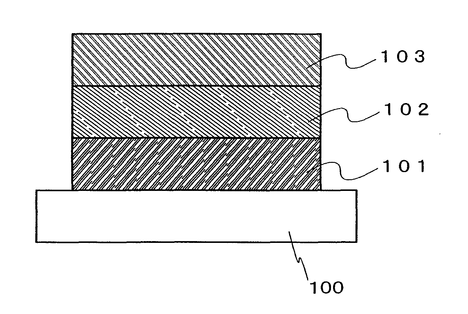
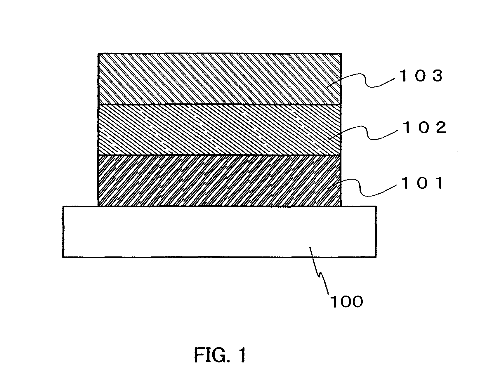
[0107]In a structure of a light emitting element of the present invention, a layer containing a light emitting material is formed between a pair of electrodes. The element structure is not limited in particular; a known structure can be appropriately selected in accordance with the purpose.

[0108]FIG. 1 schematically shows an element structure of a light emitting element according to the present invention as one example. The light emitting element shown in FIG. 1 includes a layer 102 containing a light emitting material between a first electrode 101 and a second electrode 103. The layer 102 containing a light emitting material includes an anthracene derivative of the Embodiment 1. An anode in the present invention is an electrode for injecting holes into the layer including a light emitting material. A cathode in the present invention is an electrode for injecting electr...

embodiment 3

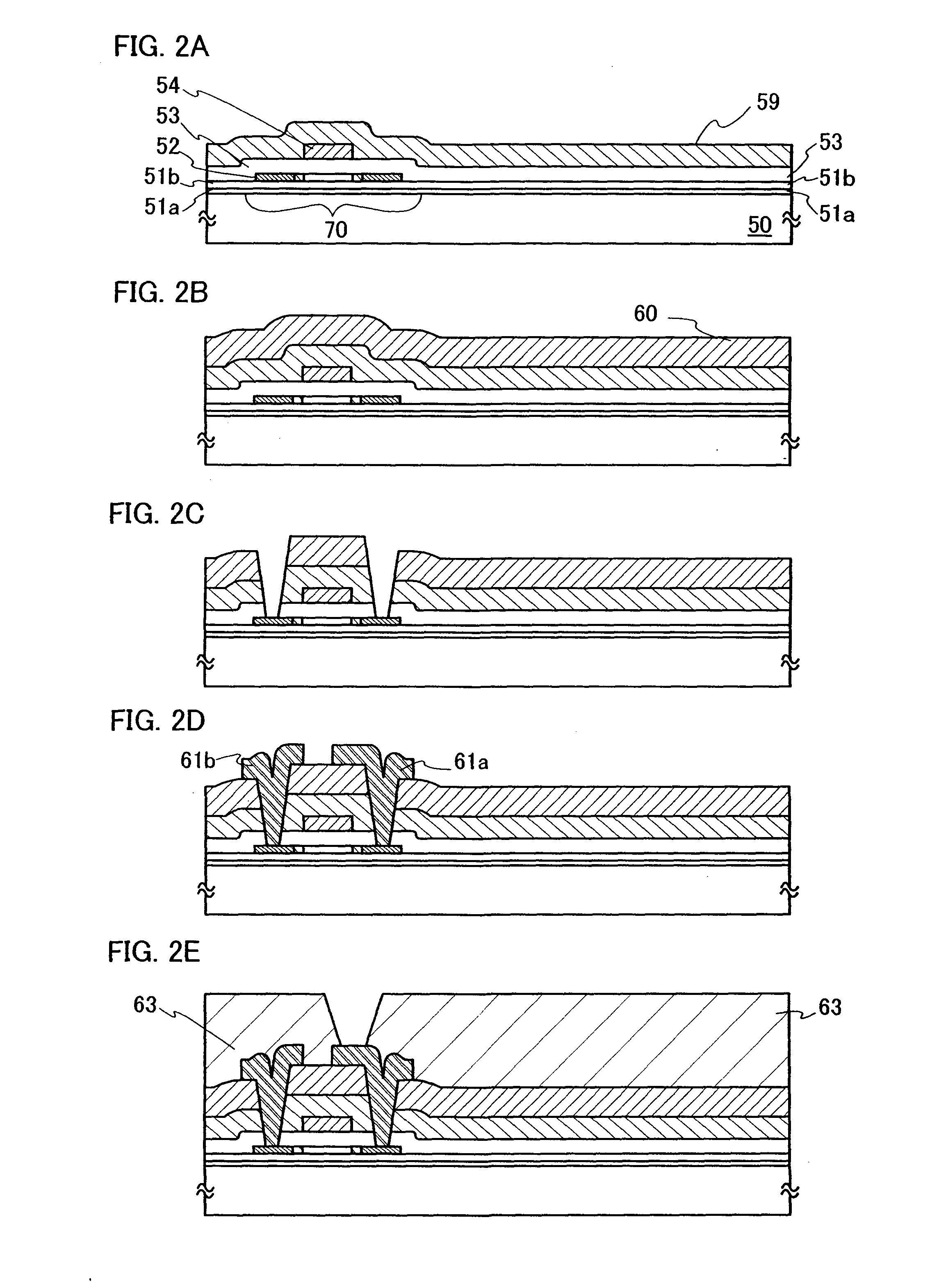
[0128]This embodiment will describe a light emitting device according to the present invention shown with reference to FIGS. 2A to 4B showing the manufacturing methods. Although this embodiment shows an example of manufacturing an active matrix light emitting device, the present invention is also applicable to a passive light emitting device.

[0129]First, a first base insulating layer 51a and a second base insulating layer 51b are formed over a substrate 50, and then a semiconductor layer is formed over the second base insulating layer 51b (FIG. 2A).

[0130]As a material of the substrate 50, glass, quartz, plastic (such as polyimide, acrylic, polyethylene terephthalate, polycarbonate, polyacrylate, or polyethersulfone), or the like can be used. These substrates may be used after being polished by CMP or the like as necessary. In this embodiment, a glass substrate is used. The first base insulating layer 51a and the second base insulating layer 51b are provided in order to prevent an el...


PUM

PropertyMeasurementUnit
Band gapaaaaaaaaaa
Band gapaaaaaaaaaa
Nanoscale particle sizeaaaaaaaaaa

Abstract

It is an object of the present invention to provide a novel material capable of realizing excellent color purity of blue, and a light emitting element and a light emitting device using the novel material. Further, it is an object of the present invention to provide which is highly reliable, and a light emitting element and a light emitting device using the novel material. The structure for solving the above problems in accordance with the present invention is an anthracene derivative simultaneously having a diphenylanthracene structure and a carbazole skeleton in a molecule as represented by structural formula (1):

Description

TECHNICAL FIELD[0001]The present invention relates to a light emitting material. Further, the present invention relates to a light emitting element having a pair of electrodes and a layer containing a light emitting material that can emit light when applied with electric field. Moreover, the present invention relates to a light emitting device having such a light emitting element.BACKGROUND ART[0002]A light emitting element using a light emitting material has advantages of thinness, lightness in weight, fast response, direct-current low-voltage driving, and so on, and is expected to be applied to a next-generation flat panel display. Further, a light emitting device having light emitting elements arranged in matrix is superior to a conventional liquid crystal display device in a wide viewing angle and high visibility.[0003]A light emitting element has the following light-emission mechanism: voltage is applied to a light emitting layer sandwiched between a pair of electrodes, so that...

Claims


Application Information

Patent Timeline
IPC IPC(8): H01J1/63C07C13/58C07D209/86C07D209/88
CPCC07D209/86C07D209/88C09K11/06C09K2211/1011H01L27/3244Y10S428/917H01L51/0061H01L51/0072H01L51/5012H05B33/14H01L51/0058H10K59/12H10K85/636H10K85/626H10K85/6572H10K50/11
Inventor KAWAKAMI, SACHIKOOHSAWA, NOBUHARUNAKASHIMA, HARUEKOJIMA, KUMISEO, SATOSHIEGAWA, MASAKAZUNOMURA, RYOJI
Owner SEMICON ENERGY LAB CO LTD
Why Eureka
Try Eureka