Backlight control device and display apparatus
- Summary
- Abstract
- Description
- Claims
- Application Information
AI Technical Summary
Benefits of technology
Problems solved by technology
Method used
Image

Examples
first embodiment
(1) First Embodiment
[0058](1-1) Configuration of Backlight Control Device
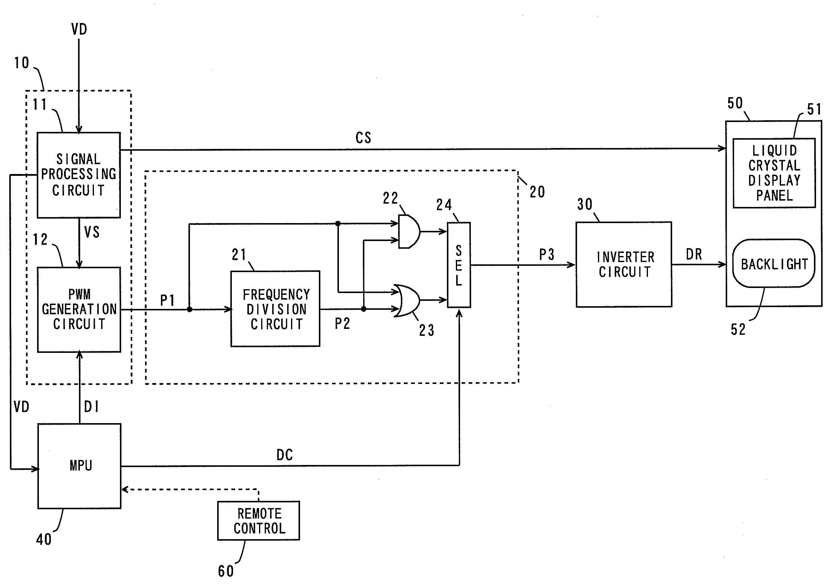
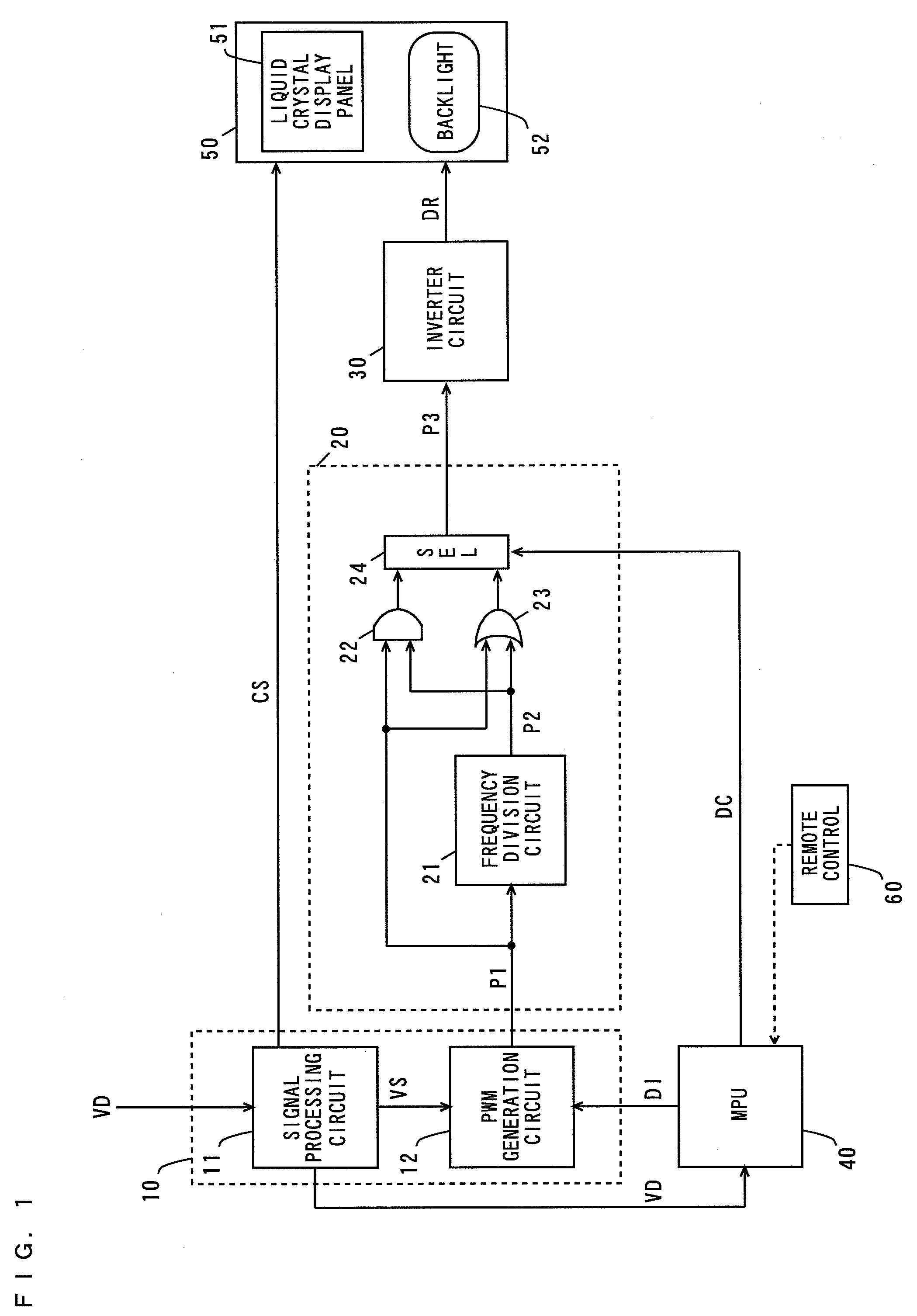
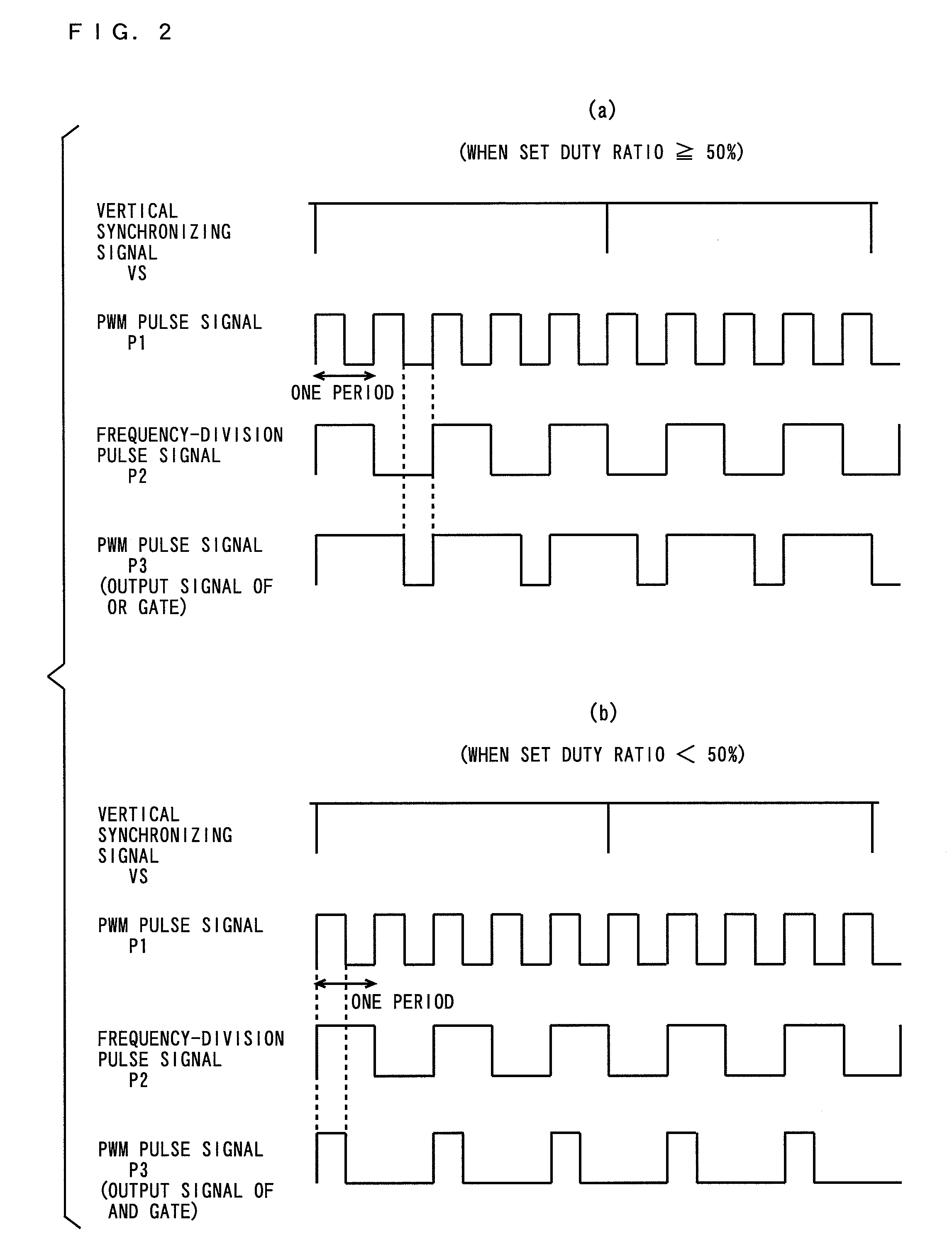
[0059]FIG. 1 is a block diagram showing the configuration of a display apparatus comprising a backlight control device according to a first embodiment of the present invention.
[0060]In FIG. 1, the display apparatus comprises a control device 10, an addition circuit 20, an inverter circuit 30, an MPU (Microprocessing Unit) 40, a liquid crystal panel module 50, and a remote control 60. The control device 10, the addition circuit 20, the inverter circuit 30, the MPU (Micro processing Unit) 40, and the remote control 60 constitute the backlight control device.
[0061]The control device 10 comprises a signal processing circuit 11 and a PWM (Pulse Width Modulation) generation circuit 12, and is composed of an LSI (Large-Scale Integrated Circuit).
[0062]The addition circuit 20 comprises a frequency division circuit 21, and an AND gate 22, an OR gate 23, and a selector 24. The liquid crystal panel module 50 comprises a li...
second embodiment
(2) Second Embodiment
[0087](2-1) Configuration of Backlight Control Device
[0088]FIG. 3 is a block diagram showing the configuration of a display apparatus comprising a backlight control device according to a second embodiment of the present invention.
[0089]The backlight control device shown in FIG. 3 differs from the backlight control device shown in FIG. 1 in that an addition circuit 20 further comprises a selector 25.
[0090]An MPU 40 feeds a duty designation signal DI to a PWM generation circuit 12 on the basis of a video signal VD or an instruction from a remote control 60 and feeds a duty control signal DC to a selector 24, and further feeds a fixed duty switching signal SD to the selector 25. The fixed duty switching signal SD controls the selection operation of the selector 25.
[0091]The selector 25 selectively outputs a PWM pulse signal P3 outputted from the selector 24 or a frequency-division pulse signal P2 outputted from a frequency division circuit 21 as a PWM pulse signal ...
third embodiment
(3) Third Embodiment
[0112](3-1) Configuration of Backlight Control Device
[0113]FIG. 5 is a block diagram showing the configuration of a display apparatus comprising a backlight control device according to a third embodiment of the present invention.
[0114]The backlight control device shown in FIG. 5 differs from the backlight control device shown in FIG. 1 in that an addition circuit 20 further comprises a mono-multi vibrator 26.
[0115]A PWM pulse signal P1 generated by a PWM generation circuit 12 is fed to the mono-multi vibrator 26. The mono-multi vibrator 26 outputs an expanded pulse signal P5 having a pulse having a predetermined width in response to the PWM pulse signal P1. Specifically, the expanded pulse signal P5 has a pulse that enters a high level for a predetermined period from the time when the PWM pulse signal P1 rises.
[0116]A frequency division circuit 21 frequency-divides the expanded pulse signal P5 generated by the mono-multi vibrator 26, to output a frequency-divisio...
PUM
 Abstract
Description
Claims
Application Information
 - Generate Ideas
- Intellectual Property
- Life Sciences
- Materials
- Tech Scout
- Unparalleled Data Quality
- Higher Quality Content
- 60% Fewer Hallucinations
Browse by: Latest US Patents, China's latest patents, Technical Efficacy Thesaurus, Application Domain, Technology Topic, Popular Technical Reports.
© 2025 PatSnap. All rights reserved.Legal|Privacy policy|Modern Slavery Act Transparency Statement|Sitemap|About US| Contact US: help@patsnap.com