MEMS microphone and method for manufacturing the same

a micro-electromagnetic system and microphone technology, applied in the field of micro-electromagnetic system microphones, can solve the problems of increasing the size of the mems microphone, time-consuming and costly etching of the large acoustic chamber in the silicon substrate,

Active Publication Date: 2009-01-15
TSINGHUA UNIV +1
View PDF6 Cites 39 Cited by
  • Summary
  • Abstract
  • Description
  • Claims
  • Application Information

AI Technical Summary

Problems solved by technology

However, since the acoustic chamber of the conventional MEMS microphone is formed by etching the silicon substrate, to form a large acoustic chamber in the conventional MEMS microphone will increase the size of the MEMS microphone, which violates the compact size and lightness requirements for the MEMS microphone.
Furthermore, to etch the large acoustic chamber in the silicon substrate is time consuming and costly.

Method used


Image

  • MEMS microphone and method for manufacturing the same
  • MEMS microphone and method for manufacturing the same
  • MEMS microphone and method for manufacturing the same

Examples


first embodiment

[0024]Reference will now be made to the drawing figures to describe the first embodiment in detail.

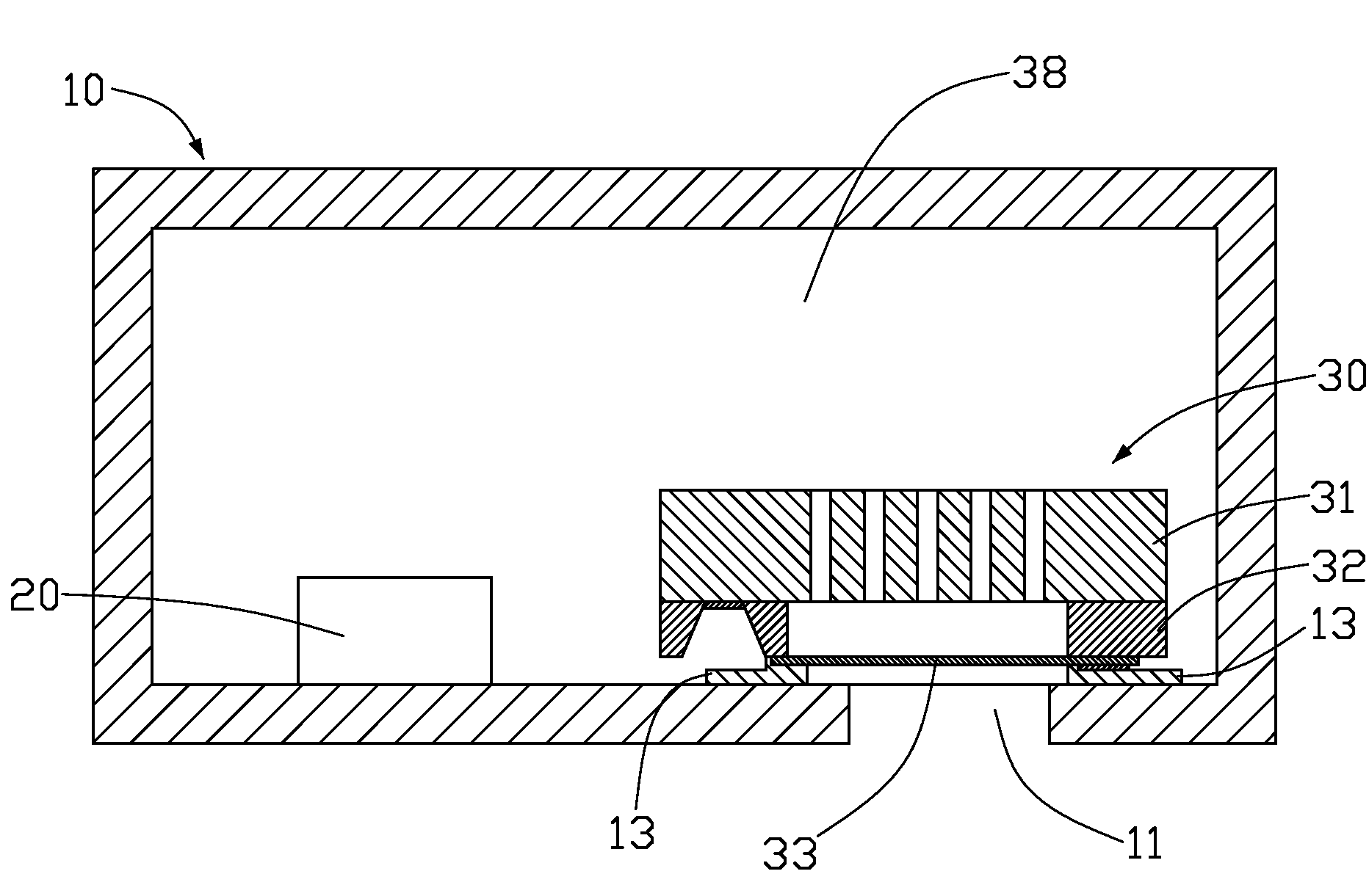
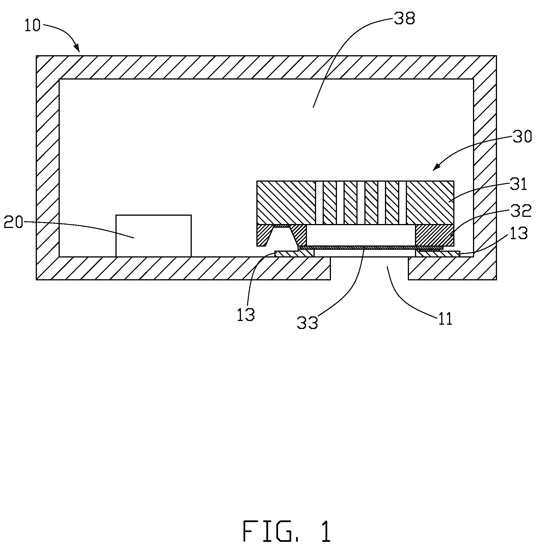
[0025]FIG. 1 is an isometric view of an MEMS (micro electromechanical system) microphone in accordance with a first embodiment of the present invention. The MEMS microphone includes a sealed casing 10, a microphone chip 30 arranged in the casing 10, and circuits 20 disposed in the sealed casing 10 and electrically connected with the microphone chip 30.

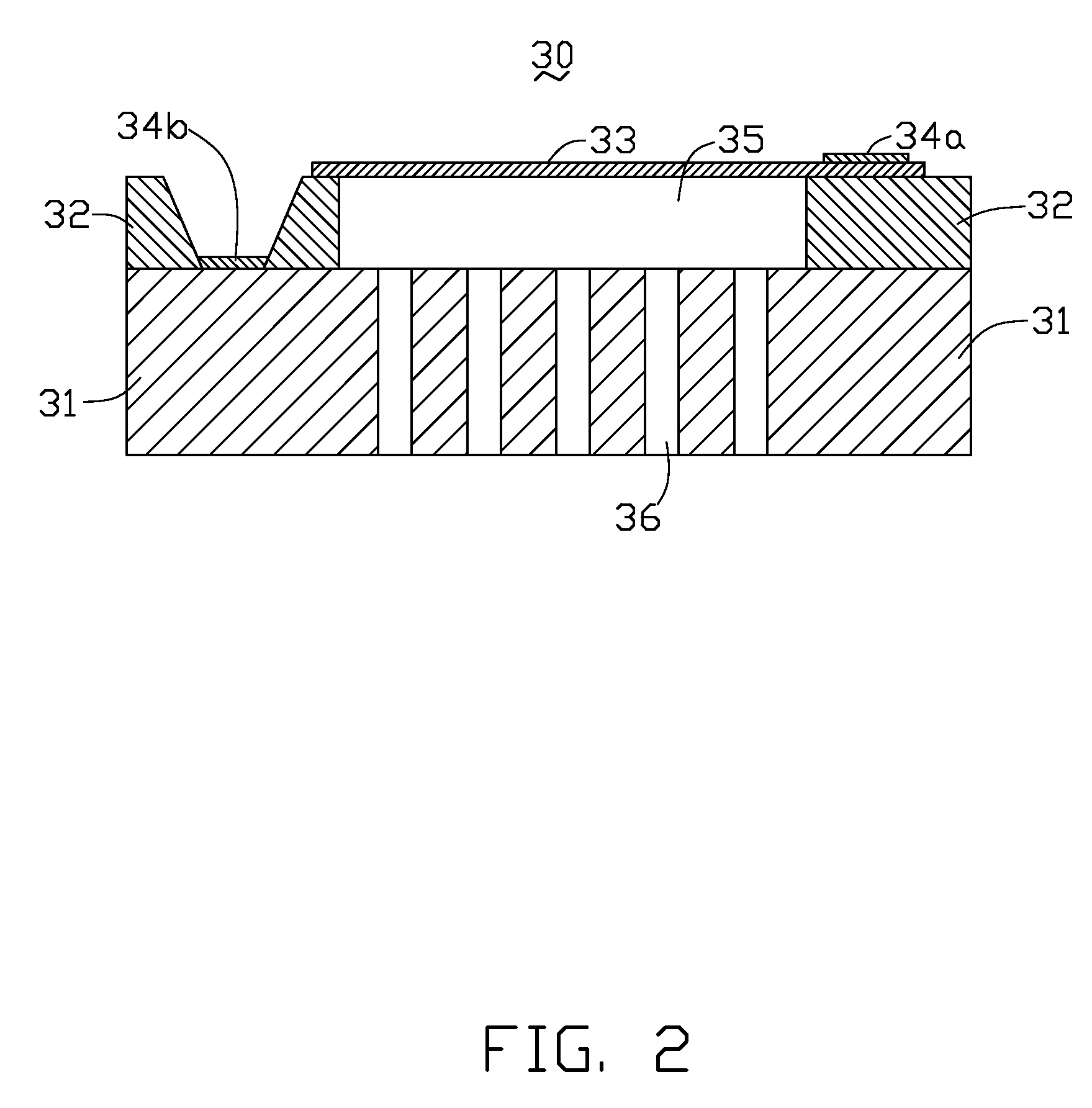
[0026]Referring to FIG. 2, the microphone chip 30 includes a back plate 31, an isolation layer 32, a flexible oscillating diaphragm 33 and first and second electrodes 34a, 34b.

[0027]The back plate 31 is made of doped P-type silicon, doped N-type silicon, or intrinsic silicon. Preferably, the back plate 31 is made of a P+-doped polysilicon. The back plate 31 functions as a fixed electrode plate and a substrate of the microphone chip 30. The isolation layer 32, the diaphragm 33, and the first and second electrodes 34a, 34b are disposed on ...

second embodiment

[0048]Referring to FIG. 20, the isolation layer 32 is etched through the holes 46 so as to form the air interstice 35 via dry etching method such as ICP (inductive coupled plasma) method or RIE (reactive ion etching) method, or wet etching method, or release-etching method. The mask layer 58d is removed from the back plate 41 so as to form the microphone chip 40 of the

[0049]Furthermore, a passivation layer 58 is deposited on the back plate 41 after the mask layer 58d is removed. The microphone chip 50 of the third embodiment is obtained. Alternatively, the mask layer 58d can function as the passivation layer 58 of the third embodiment. In this case, there is no need to get rid of the mask layer 58d from the back plate 41.

[0050]In the present methods, the microphone chip 30 of the first embodiment can be made by the method shown in FIGS. 16 to 20. Under this status, there is no need to form the assistant conductive layer 47 on the silicon substrate 41d of FIG. 16. Similarly, the micr...


PUM


Abstract

An MEMS microphone includes a casing (10) and a microphone chip (30) disposed in the casing. The casing defines a sound entrance (11) therein. The microphone chip includes a back plate (31), an isolation layer (32) and a diaphragm (33). The isolation layer separates the back plate from the diaphragm so as to form an air interstice (35) therebetween. The back plate and the diaphragm electrically connect with two electrodes (34a, 34b), respectively. The back plate defines a plurality of holes (36) therethrough. The holes communicate the air interstice with a sealed acoustic chamber (38) between the casing and the microphone chip. The diaphragm is adhered to an inner side of the casing at a position over the sound entrance.

Description

BACKGROUND OF THE INVENTION[0001]1. Field of the Invention[0002]The present invention relates generally to microphones, and more particularly to an MEMS (micro electromechanical system) microphone and method for manufacturing the same.[0003]2. Description of Related Art[0004]Sound is one important means by which people communicate with each other, thus creating new methods for sound transference which allows greater communication between people is an important area of technological development. Electroacoustic transducers are key components in transferring sound. Microphone is a typical electroacoustic transducer. There are many different types of microphones, such as ECM (electric condenser microphone), or MEMS (micro electromechanical system) microphone.[0005]An MEMS microphone includes a casing, a microphone chip arranged in the casing, and circuits (not shown) disposed in the casing and electrically connected with the microphone chip. The microphone chip includes an oscillating ...

Claims


Application Information

Patent Timeline
Patent Type & Authority Applications(United States)
IPC IPC(8): H04R9/00
CPCB81B2201/0257H04R19/04B81C1/00182
Inventor QIAO, DONG-HAI
Owner TSINGHUA UNIV
Why Eureka
Try Eureka