Composite Water Management Electrolyte Membrane For A Fuel Cell

a fuel cell and electrolyte membrane technology, applied in the field of fuel cells, can solve the problems of increasing hydrophilic carbon within the microporous region, electrically conductive carbon within the membrane not providing a short circuit between the catalysts, etc., to facilitate enhanced water management, facilitate hydration of the pem, and effectively remove water

Inactive Publication Date: 2009-01-15
AUDI AG +2
View PDF9 Cites 3 Cited by
  • Summary
  • Abstract
  • Description
  • Claims
  • Application Information

AI Technical Summary

Benefits of technology

[0007]In a preferred embodiment, the composite electrolyte membrane is secured within the fuel cell so that the microporous region is disposed adjacent the first contact surface of the membrane and the first contact surface of the membrane is secured adjacent a cathode electrode catalyst of the fuel cell. In this embodiment, the larger pores of the microporous region of the membrane will be closest to the cathode catalyst, while smaller nanopores within only the ionomer component are closest to the anode catalyst. By this arrangement, the composite electrolyte membrane serves as a water sink for product water generated at the cathode catalyst, while the finer pores closest to the anode catalyst will serve to draw the water by capillary action from the larger pores toward the smaller pores adjacent the anode catalyst to thereby facilitate hydration of the PEM adjacent the anode catalyst.
[0008]In a further embodiment, the structural matrix may be selected to be the same material as structural material supporting the catalysts, such as carbon. Therefore, as the carbon support of the catalysts becomes increasingly hydrophilic over prolonged usage of the fuel cell, the carbon within the microporous region will also become increasingly hydrophilic. Because the microporous region is between the two catalysts, product water at the cathode catalyst will therefore be drawn into the hydrophilic carbon of the microporous region to effectively remove water from the cathode catalyst that could otherwise flood the cathode and impede flow of oxidant by the cathode.
[0009]Moreover, because the microporous region does not extend between the opposed contact surfaces of the membrane, the electrically conductive carbon within the membrane will not provide a short circuit between the catalysts. Further alternative embodiments provide for varying dispositions of the microporous region within the membrane to facilitate enhanced water management for specific operating requirements of varying types of fuel cells.

Problems solved by technology

Therefore, as the carbon support of the catalysts becomes increasingly hydrophilic over prolonged usage of the fuel cell, the carbon within the microporous region will also become increasingly hydrophilic.
Moreover, because the microporous region does not extend between the opposed contact surfaces of the membrane, the electrically conductive carbon within the membrane will not provide a short circuit between the catalysts.

Method used


Image

  • Composite Water Management Electrolyte Membrane For A Fuel Cell
  • Composite Water Management Electrolyte Membrane For A Fuel Cell

Examples


Embodiment Construction

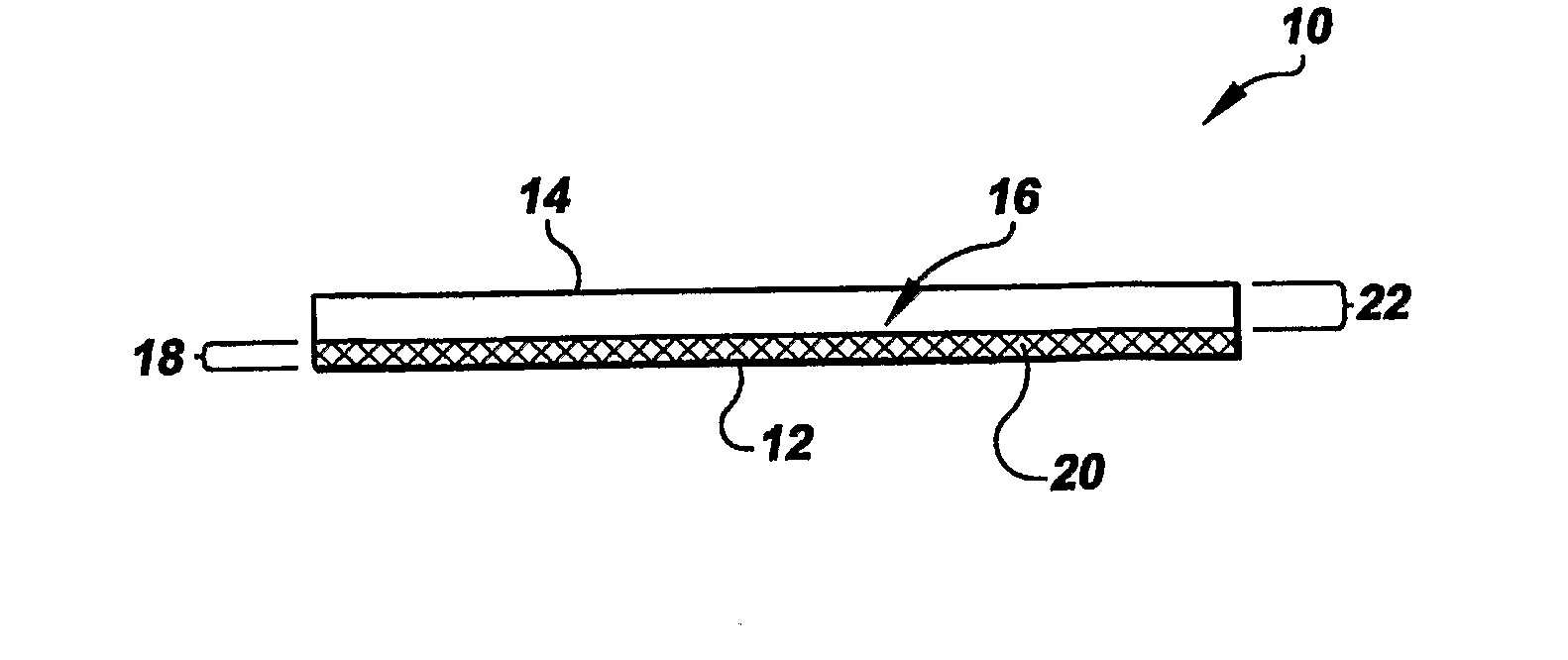
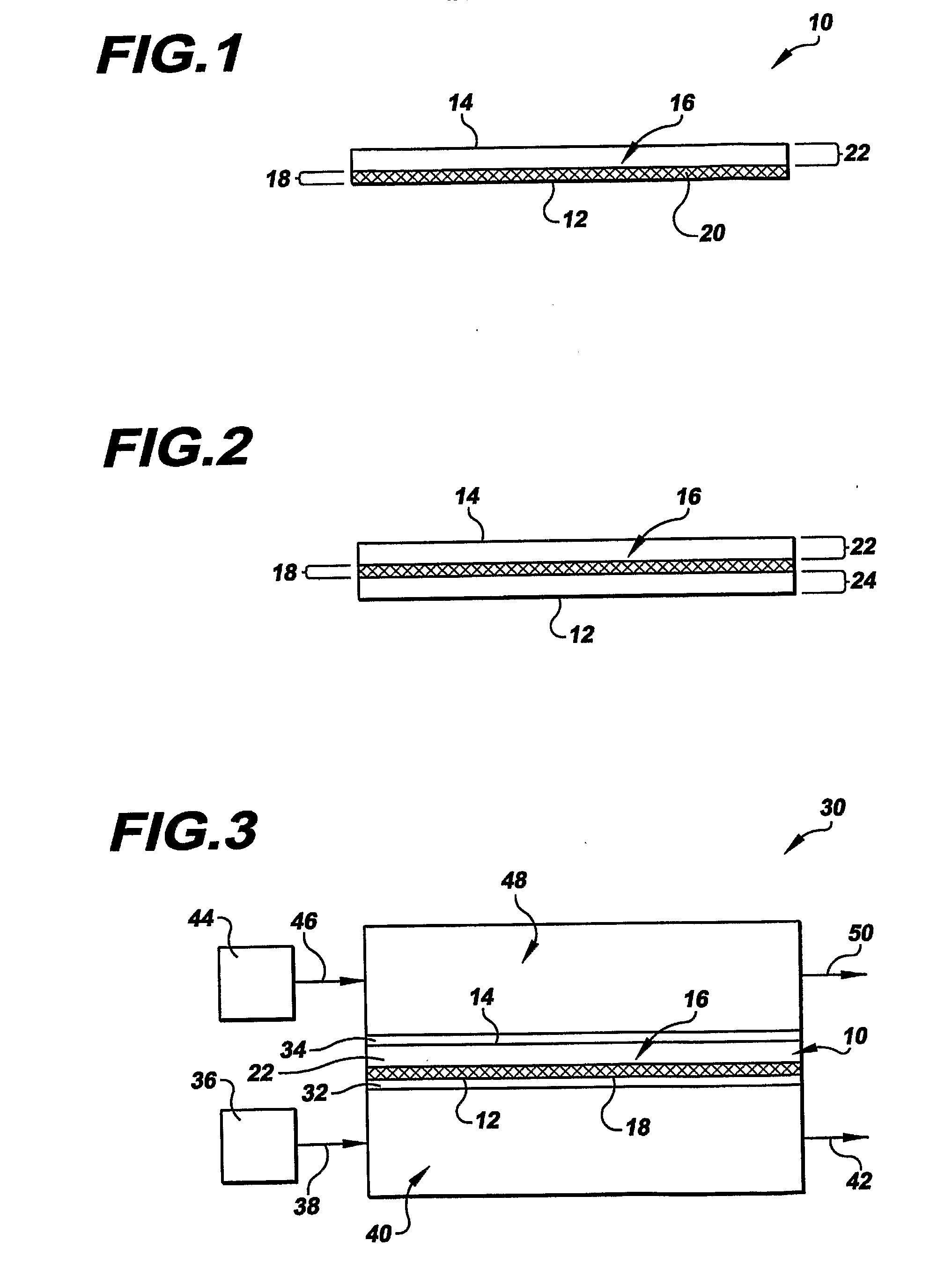
[0016]Referring to the drawings in detail, a composite electrolyte membrane is shown in FIG. 1, and is generally designated by the reference numeral 10. The membrane 10 defines a first contact surface 12 and an opposed second contact surface 14. (By the phrase “contact surface”, it is meant that the membrane 10 is a generally flat, disk-shaped construction, and the “contact surfaces” of the membrane 10 are constructed to be positioned in intimate contact with adjacent layers of a fuel cell, as opposed to being at a perimeter of the membrane 10.) An ionomer component 16 extends continuously between the contact surfaces 12, 14 of the membrane. A microporous region 18 is defined within the ionomer component 16 between the first and second contact surfaces 12, 14. The ionomer component 16 is a hydrated nanoporous ionomer that consists of any suitable cation exchange resin that is compatible with an operating environment of an electrochemical cell. An exemplary material for constituting ...


PUM

PropertyMeasurementUnit
diameteraaaaaaaaaa
diameteraaaaaaaaaa
diameteraaaaaaaaaa

Abstract

A composite electrolyte membrane (10) for a fuel cell (30) includes an ionomer component (16) extending continuously between opposed first and second contact surfaces (12, 14) defined by the membrane (10). The ionomer component is a hydrated nanoporous ionomer consisting of a cation exchange resin. The membrane (10) also includes a microporous region (18) consisting of the ionomer compound (16) and a structural matrix (20) dispersed through region (18) within the ionomer compound (16) to define open pores having a diameter of between 0.3 and 1.0 microns. The microporous region (18) does not extend between the contact surfaces (12, 14), and facilitates water management between the electrode catalysts (32, 34).

Description

TECHNICAL FIELD[0001]The present invention relates to fuel cells that are suited for usage in transportation vehicles, portable power plants, or as stationary power plants, and the invention especially relates to a composite electrolyte membrane that facilitates water management within a fuel cell.BACKGROUND ART[0002]Fuel cells are well known and are commonly used to produce electrical power from hydrogen containing reducing fluid fuel and oxygen containing oxidant reactant streams to power electrical apparatus such as generators and transportation vehicles. In fuel cells of the prior art, it is known to utilize a proton exchange membrane (“PEM”) as the electrolyte. As is well known, protons formed at the anode electrode move through the electrolyte to the cathode electrode, and it is generally understood that for each proton moving from the anode side to the cathode side of the electrolyte, approximately three molecules of water are dragged with the proton to the cathode side of th...

Claims


Application Information

Patent Timeline
Patent Type & Authority Applications(United States)
IPC IPC(8): H01M8/00H01M4/00
CPCH01M8/04291H01M8/1004Y02E60/521H01M8/106H01M8/1062H01M8/1053Y02E60/50
Inventor DARLING, ROBERT M.PERRY, MICHAEL L.
Owner AUDI AG
Why Eureka
Try Eureka