Expansion Valve and Air Conditioner

a technology of expansion valve and expansion valve, which is applied in the direction of refrigeration components, lighting and heating equipment, instruments, etc., can solve the problems of generating noise in the expansion valve, affecting the operation of the expansion valve, and unable to operate at a regular pressure, etc., and achieves the effect of easy vibration, easy excitation and easy vibration

Inactive Publication Date: 2009-01-22
KOKUSA ELECTRIC CO LTD +1
View PDF3 Cites 8 Cited by
  • Summary
  • Abstract
  • Description
  • Claims
  • Application Information

AI Technical Summary

Benefits of technology

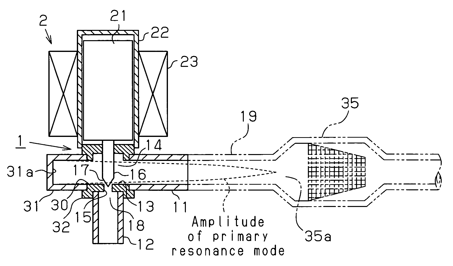
[0008]In such a piping connected to the restricting portion and filled with a substantially liquid refrigerant, a resonance space as shown in FIG. 9 is assumed. FIG. 9 is an arrangement example of piping 112 connected to a restricting portion 111 of an expansion valve 110 and filled with a substantially liquid refrigerant. A filter 113 is connected to the piping 112. In the resonance space of the piping in this case, a resonance mode may occur in which a side wall 114a of a valve chamber 114 of the expansion valve 110 serves as a closed end, and a large diameter portion 113a of the filter 113 in the piping 112 connected to a piping connecting portion serves as an open end. As shown in FIG. 9, the amplitude of the resonance mode is maximized at the closed end position (what is called an antinode), and the amplitude of the resonance mode becomes zero at the open end position (what is called a node). On the other hand, a noise source in the expansion valve 110 appears to result from turbulence of the refrigerant around the restricting portion 111. The restricting portion 111 is easily subjected to vibration since it exists in the antinode position of the above-described resonance mode. Therefore, the resonance mode is easily excited due to application of energy of the high speed refrigerant passing through the restricting portion 111.
[0009]FIGS. 10(a) to 10(c) are schematic diagrams of resonance modes showing images of amplitudes of various sizes by dashed lines. In the piping 112 connected to the restricting portion 111 and filled with a substantially liquid refrigerant, every resonance mode, not only a primary mode shown in FIG. 9 or 10(a) but also a secondary mode and a tertiary mode shown in FIGS. 10(b) and 10(c), is vibrated easily. The present inventor found that adjustment of resonance characteristics in a resonance space, in particular, adjustment of moving an antinode position of a resonance mode allows for a reduction of the amplitude level in acoustic resonance although the position of the restricting portion 111 cannot be changed. Further, it has been found that resonance characteristics are dependent on system design of air conditioners, from the fact that resonance modes in an actual device are determined by characteristics of every cross-sectional area varying portion of components connected to an expansion valve, for example, a filter, a silencer, a heat exchanger and by states of a circulating refrigerant, etc. In other words, the present inventor discovered that adjustment of resonance characteristics varies according to system design of air conditioners.

Problems solved by technology

However, a study by the present inventor discovered that noise in the expansion valve is generated not only in the aforementioned cases.
Upon condensation, liquefaction and accumulation of the refrigerant in the indoor heat exchanger 108, the refrigerant amount within the refrigerant circuit runs short, which renders the operation at a regular pressure impossible and then leads to a possibility of constituting a hindrance to the heating operation.

Method used


Image

  • Expansion Valve and Air Conditioner
  • Expansion Valve and Air Conditioner
  • Expansion Valve and Air Conditioner

Examples


first embodiment

[0029]Hereinafter, an expansion valve according to a first embodiment of this invention is described with reference to FIG. 1. FIG. 1 is a longitudinal cross-sectional view of the expansion valve according to the first embodiment. The expansion valve according to the present embodiment is composed of a valve body 1 and a valve actuator 2 mounted on an upper part of the valve body 1 as shown in FIG. 1.

[0030]The valve body 1 has piping connection portions 11, 12 on a side surface and an under surface thereof, respectively. A refrigerant flow passage is formed between the piping connection portions 11, 12. The refrigerant flow passage is partitioned by a valve seat 13, and a valve chamber 14 is defined on an upper part of the valve seat 13. A valve hole 15 is formed in the valve seat 13, and a needle valve 17 formed at a distal end of a valve stem 16 is configured so as to be move from above relative to the valve hole 15. The needle valve 17 and the valve seat 13 constitute a restricti...

second embodiment

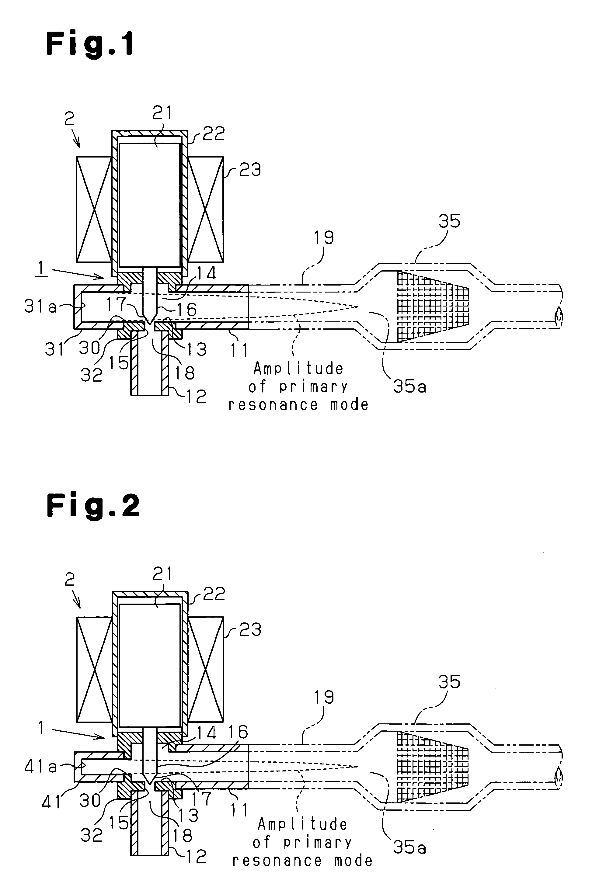
[0038]In an expansion valve according to a second embodiment, a resonance adjuster 41 with a smaller diameter than the piping 19 is used instead of the resonance adjuster 31 according to the first embodiment, as shown in FIG. 2. The closed end of the resonance space in this case corresponds to a closed end 41a of the resonance adjuster 41 attached to the outside of the valve body 1. A basic concept of the resonance adjuster 41 according to the second embodiment is identical to that of the resonance adjuster 31 of the first embodiment. Adjustment of the length and the diameter of the resonance adjuster 41 allows for adjustment of resonance characteristics, and the amplitude level of noise due to acoustic resonance id lowered to reduce resonance sound.

third embodiment

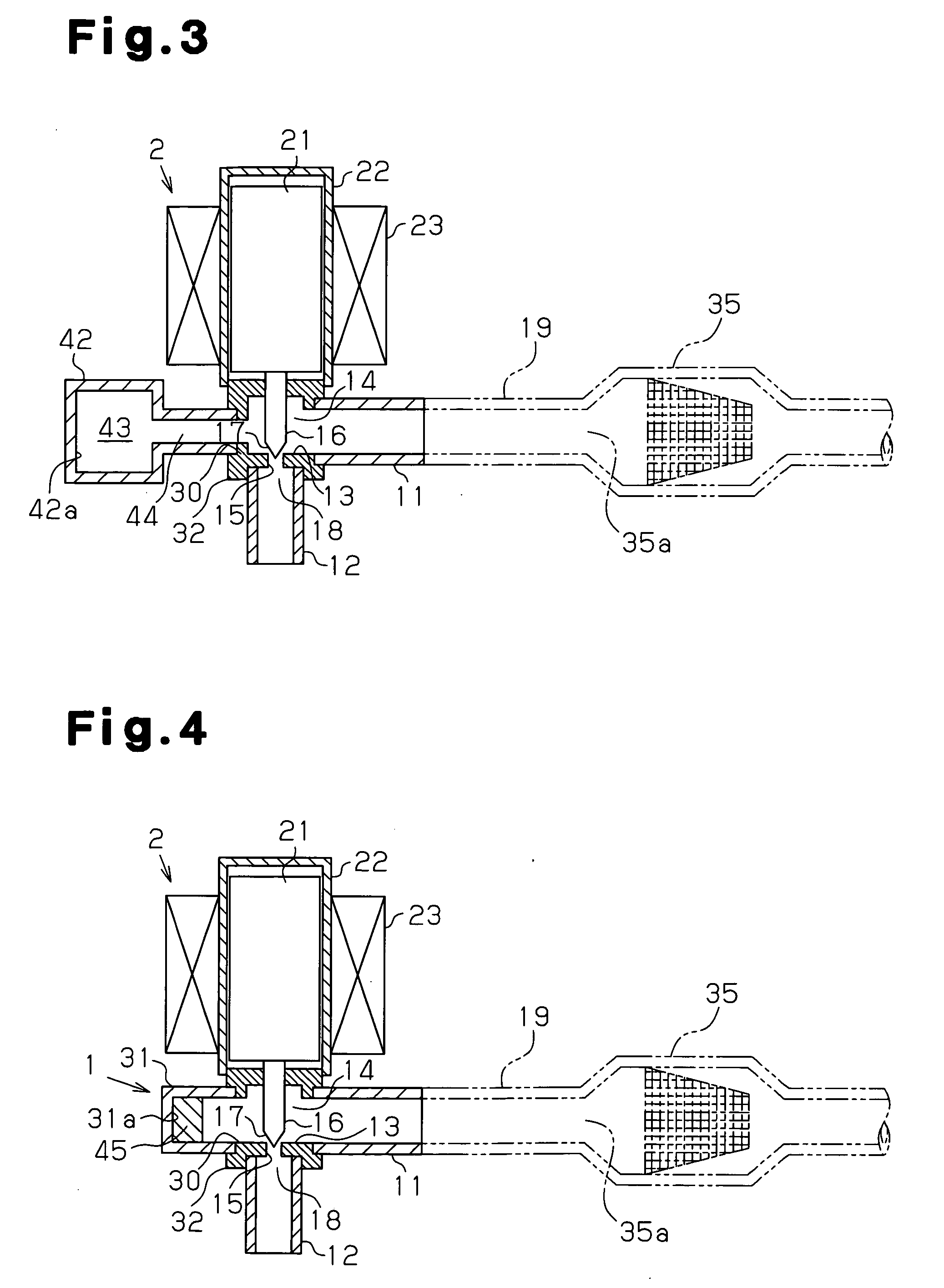
[0039]A resonance adjuster 42 according to a third embodiment includes an enclosed space (noise absorbing chamber) 43 and a communication path 44 communicating with the space 43 and having a predetermined length and a predetermined cross-sectional area, as shown in FIG. 3. The resonance adjuster 42 is coupled laterally to the valve chamber 14, whereby the closed end of the resonance space corresponds to a closed end 42a of the resonance adjuster 42 attached to the outside of the valve body 1. The expansion valve according to the third embodiment can adjust resonance characteristics of the piping 19 and lower a noise level of low frequencies by being attached with the resonance adjuster 42 having the foregoing configuration. Therefore, the amplitude level of resonance sound is further reduced.


PUM


Abstract

An expansion valve capable of reducing noise due to acoustic resonance by allowing for adjustment of resonance characteristics of piping connected to a restricting portion and filled with a substantially liquid refrigerant, and an air conditioner using the same are provided. The expansion valve has a valve body 1, a restricting portion 18 formed inside the valve body 1, two piping connection portions 11, 12 communicating with the upstream side and the downstream side of the restricting portion 18, and at least one opening 30 that opens a refrigerant flow passage to outside of the valve body 1, the refrigerant flow passage extending from the piping connection portion 12 to which a piping 19 filled with a substantially liquid refrigerant is connected to the restricting portion 18. The valve body 1 is formed in such a manner that a resonance adjuster 31 having a resonance space and adjusting resonance characteristics of the piping 19 filled with a substantially liquid refrigerant can be attached to the outside so as to communicate with the opening 30.

Description

TECHNICAL FIELD[0001]The present invention relates to an expansion valve which is used in a general refrigerating cycle, expands a high-temperature and high-pressure refrigerant to convert it into a low-temperature and low-pressure refrigerant, and to an air conditioner using the same.BACKGROUND ART[0002]Conventionally, noise reduction in air conditioning systems has been demanded, and in particular, lowering noise in an expansion valve has been required. As a noise problem in an expansion valve, attention has mainly been given to noise in a case where a refrigerant flow that flows into the expansion valve becomes a gas-liquid two phase flow due to factors such as an increase in refrigerant flow resistance at a position upstream of the expansion valve and deficiency in performance of a condenser. In this noise generation mechanism, refrigerant at different degrees of density irregularly passes through the interior of a valve body of the expansion valve. As a result, the pressure in ...

Claims


Application Information

Patent Timeline
Patent Type & Authority Applications(United States)
IPC IPC(8): F25B41/04G10K11/00
CPCF25B13/00F25B41/062Y02B30/72F25B2500/12F25B2341/065Y02B30/70F25B41/34F25B41/35
Inventor YUKIMOTO, TOORU
Owner KOKUSA ELECTRIC CO LTD
Why Eureka
Try Eureka