Nasal dilator with cushion layer and variable spring rate

a dilator and cushion layer technology, applied in the field of nasal dilators, can solve the problems of breathing difficulty and discomfort, loss of conditioning effects, irritation of throat and lungs, etc., and achieve the effect of enhancing the performance of the dilator

Inactive Publication Date: 2009-01-22
INFINITE FINANCIAL SOLUTIONS
View PDF39 Cites 14 Cited by
  • Summary
  • Abstract
  • Description
  • Claims
  • Application Information

AI Technical Summary

Benefits of technology

[0028]The improvements summarized above enhance the performance of the dilator and make the dilator more c

Problems solved by technology

Blockage of the nasal passages from swelling due to allergies, colds and physical deformities can lead to breathing difficulty and discomfort.
This means that the air bypasses the mucus membranes, losing the conditioning effects and causing irritation in the throat and lungs.
At night, restrictions to breathing through the nasal passages can lead to snoring and/or sleep disturbances.
In some cases, the restricted air supply can cause sleep problems brought on by a lack of oxygen.
For people with chronic blockages in the nasal passages, the alternative to correct the problem has been expensive surgery or med

Method used


Image

  • Nasal dilator with cushion layer and variable spring rate
  • Nasal dilator with cushion layer and variable spring rate
  • Nasal dilator with cushion layer and variable spring rate

Examples


Embodiment Construction

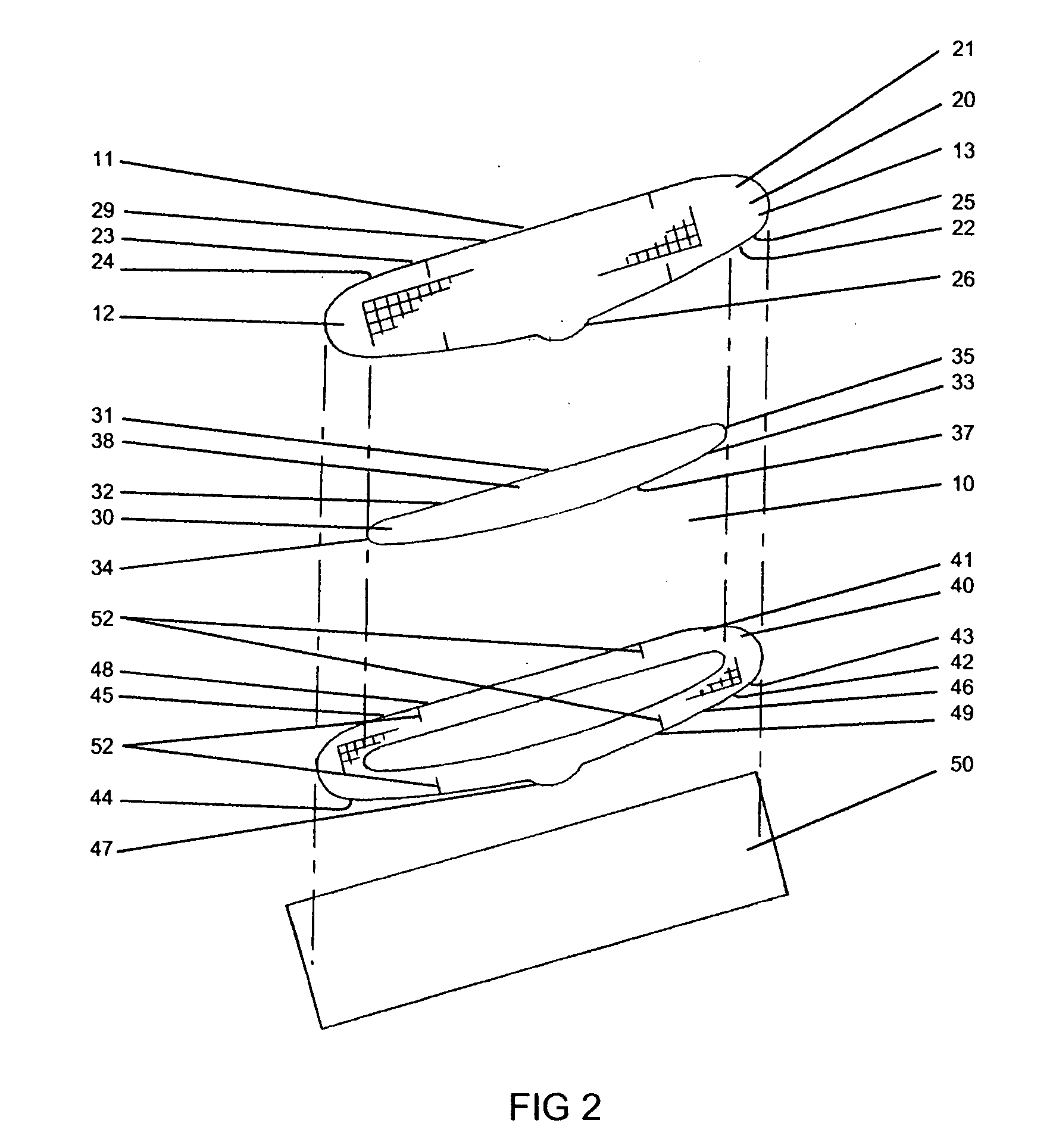
[0037]The specific improvements provided by this invention over past nasal dilators described in the prior art are best seen in the attached drawings.

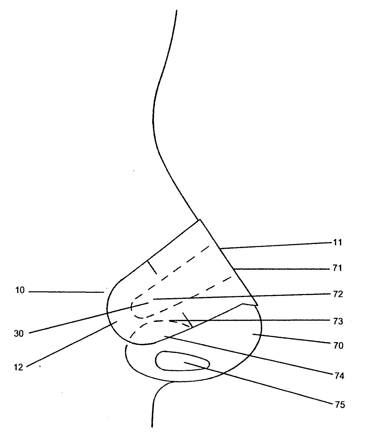
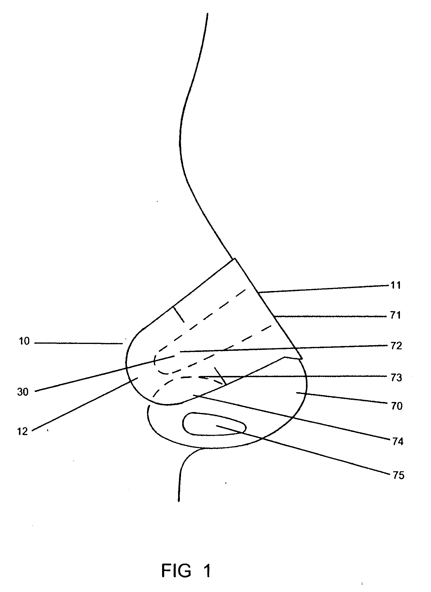
[0038]Referring to FIGS. 1-4, the new nasal dilator 10 is mounted on the nose 70 of the user. The nasal dilator 10 has a center 11 that is bent over the bridge 71 of the nose 70, and each end 12 and 13 of the nasal dilator 10 is positioned over the lateral wall 72 of the nose 70.

[0039]The lateral wall 72 of the nasal passage 75 is located in the soft tissue 73 above the nostril flare 74, which in turn is adjacent to the entrance of the nasal passage 75. When the nasal dilator 10 which contains a resilient band 30 is deformed from its normally planar state by being bent over the bridge 71 of the nose 70, the ends 12 and 13 which are attached to the lateral wall 72 of the nasal passage 75 tend to pull on the lateral wall 72 in a way that opens the nasal passage 75 and improves the air flow through the nasal passages 75 during breathing. ...


PUM


Abstract

A nasal dilator capable of introducing separating stresses in nasal outer wall tissues has a resilient member and a pair of spaced-apart end surfaces which can be forced toward one another from an initial flat position of the dilator to thereby substantially reduce the direct spacing therebetween by an external spacing reducing force. This results in restoring forces in the dilator tending to return it to the original direct spacing between the end surfaces. Resilient members, which can be asymmetrical with respect to a centerline of the dilator that is parallel to the long axis of the dilator, have a spring rate which continuously diminishes from the centerline to the end surfaces. The edges of the resilient members are contiguous to the edge of the cushion layer so that adhesive on the cushion layer is at the same level as the bottom surface of the resilient members. An adhesive on the end surfaces adhesively engages exposed surfaces of nasal outer wall tissues sufficiently to keep the dilator attached to the nasal wall surfaces while subjecting them to the restoring forces.

Description

BACKGROUND OF THE INVENTION[0001]This invention relates to an improvement to the configuration of nasal dilators such as those described in Spanish Patent No. 289,561 to Iriarti dated 15 Sep. 1986 and in the further patents discussed below. Generally speaking these dilators employ a resilient band which has an adhesive on the bottom side and sufficient length so that the resilient band can be bent over the bridge of the nose, and each end of the band becomes adhesively attached to the soft tissue on the lateral wall of the nasal passage.[0002]Bending the resilient band from its initial planar state to its deformed state with its ends in contact with the lateral walls of the nasal passages and the center of the band overlying the bridge of the nose results in forces tending to pull out on the lateral wall tissues which stabilize the walls of the nasal passages during breathing.[0003]The present invention improves nasal dilators by providing them with a resilient member which has a va...

Claims


Application Information

Patent Timeline
IPC IPC(8): A62B9/06
CPCA61F5/08
Inventor LOCKWOOD, JR., HANFORD N.
Owner INFINITE FINANCIAL SOLUTIONS
Why Eureka
Try Eureka