Methods and systems for compensating for changes in anatomy of radiotherapy patients

Active Publication Date: 2009-01-22
ELEKTA AB
View PDF99 Cites 27 Cited by
  • Summary
  • Abstract
  • Description
  • Claims
  • Application Information

AI Technical Summary

Benefits of technology

[0011]The present invention provides systems and methods for improving imaging for IGRT. Embodiments of the invention rely on the integration and use of multiple modalities in the treatment room, registered to a common coordinate system, in order to modify treatment parameters.
[0012]In one aspect, the invention combines portal images and 3D ultrasound to determine a patient shift to be applied during radiotherapy treatment. A set of baseline radiotherapy treatment parameters are established, and, during therapy, two or more registered images of the area under treatment are taken, with at least some of the images being portal images taken from at least one beam direction, and at least one of the images being a non-x-ray-based 3D image. The images are then registered to a coordinate system associated with a treatment device. The non-x-ray-based 3D image is segmented to form a 3D surface, which is projected onto the plane of each portal image, thereby enhancing the portal images with data from the projected surface. The baseline treatment parameters are then updated based on the registered images. In this fashion, new portal images are produced which incorporate the anatomy extracted

Problems solved by technology

Although CT scans provide a good physical map of electron density within the patient, they also have limitations.
For example, CT scans are devoid of functional information about tumors and provide poor soft-tissue contrast for some organs.
Although effective, ART is not generally undertaken because re-planning is time-consuming and must be validated and approved for each session.
Due to the high energy (megavolt range) of the treatment beam, image quality is generally inferior to diagnostic (kilovolt range) x-ray images, and provides little or no soft-tissue contrast.
The use of seeds is invasive, however, and the resulting images

Method used


Image

  • Methods and systems for compensating for changes in anatomy of radiotherapy patients
  • Methods and systems for compensating for changes in anatomy of radiotherapy patients
  • Methods and systems for compensating for changes in anatomy of radiotherapy patients

Examples


Embodiment Construction

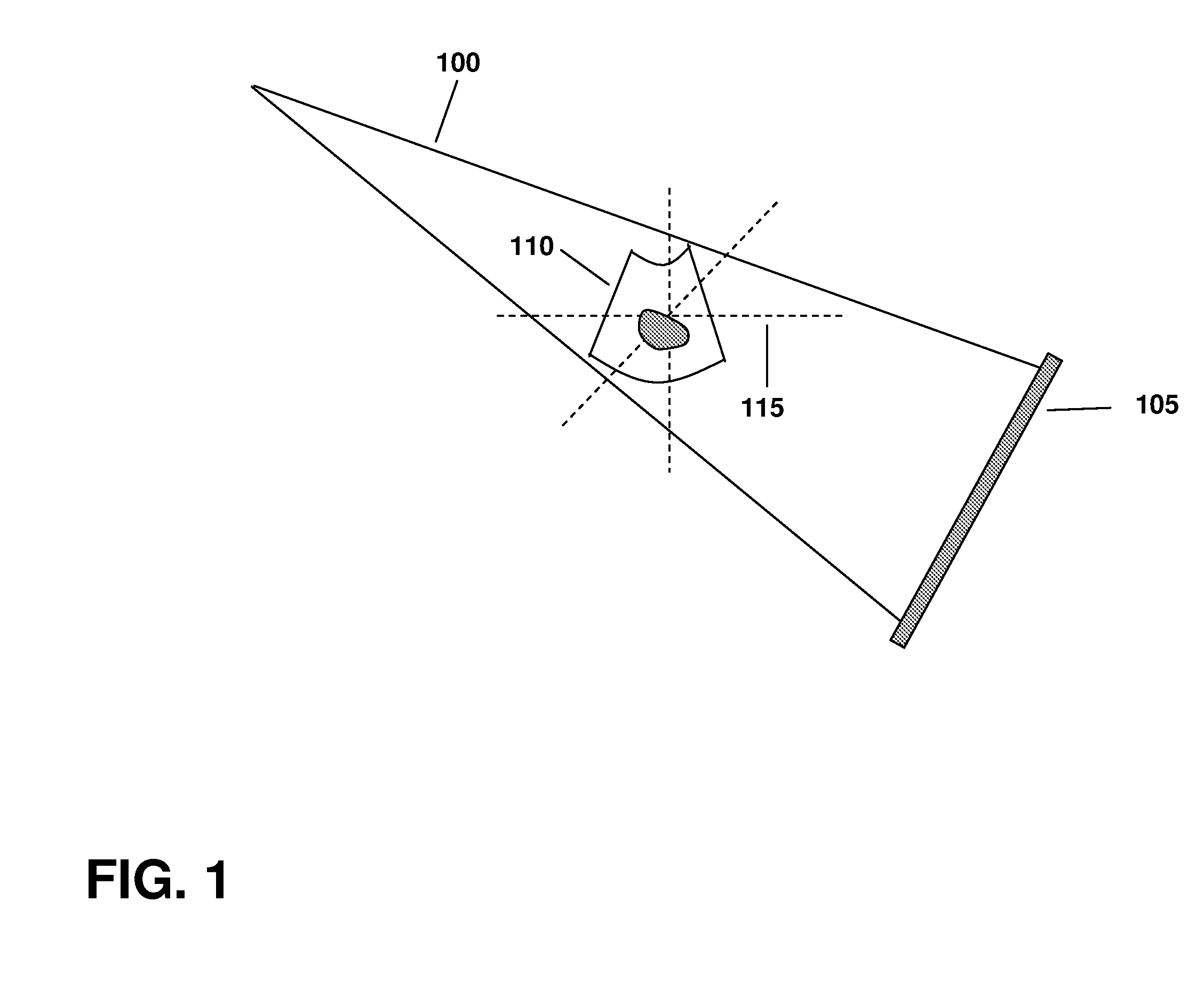
[0020]In FIG. 1, which illustrates an embodiment of the invention, the beam 100 of a linear accelerator (not shown), at a known gantry angle, is used in combination with a portal imager 105 to form a 2D image of the patient. The gantry angle may then be changed, and another image acquired. Typically at least two images are acquired from different directions using the portal imager 105. The portal imager 105 is preferably an EPID, producing digital images using the treatment beam 100. The portal images may be stored in a computer. A 3D ultrasound image 110 is also acquired, before or after the portal images but within as close a time frame as possible so that the patient does not move significantly. The portal and ultrasound images may be calibrated to a common coordinate system 115 whose origin coincides with the mechanical isocenter of the linear accelerator. This coordinate system 115 may be identified using perpendicular lasers passing through the origin. Systems and methods for ...


PUM


Abstract

Portal images are combined with 3D ultrasound to determine adjustments to patient treatment parameters. The images are acquired while the patient is in an initial position, and the images are registered to a treatment coordinate system. The images are combined and outlines of anatomical structures are superimposed on the portal images, resulting in new portal images that incorporate the anatomy extracted from the ultrasound. The enhanced portal images are used to identify modifications to the treatment parameters.

Description

CROSS-REFERENCE TO RELATED APPLICATIONS[0001]This application claims priority to and the benefit of U.S. provisional patent application Ser. No. 60 / 951,005, filed Jul. 20, 2007, the disclosure of which is incorporated herein by reference in its entirety.TECHNICAL FIELD[0002]This invention relates to methods and systems for using imaging to guide radiotherapy treatments.BACKGROUND INFORMATION[0003]Radiation therapy relies on devising a treatment plan, which includes the arrangement of therapeutic radiation beams, patient positioning relative to the beams, beam energies, apertures, and doses, and other factors. Typically, the treatment plan is based on a three-dimensional (3D) computed tomography (CT) dataset acquired prior to the first treatment session. Although CT scans provide a good physical map of electron density within the patient, they also have limitations. For example, CT scans are devoid of functional information about tumors and provide poor soft-tissue contrast for some ...

Claims


Application Information

Patent Timeline
IPC IPC(8): G06K9/00A61N5/10
CPCA61N5/1049A61N5/1065A61N2005/1054A61N2005/1058A61B6/583G06T2207/10072G06T2207/10116G06T2207/30004G06T7/0024G06T7/30
Inventor FALCO, TONYLACHAINE, MARTIN
Owner ELEKTA AB
Why Eureka
Try Eureka