Surface wave excitation plasma generator and surface wave excitation plasma processing apparatus

Inactive Publication Date: 2009-01-29
SHIMADZU CORP
View PDF4 Cites 11 Cited by
  • Summary
  • Abstract
  • Description
  • Claims
  • Application Information

AI Technical Summary

Benefits of technology

[0014]According to the present invention, the construction and size of the annular microwave waveguide having an end part can be optimized with respect to the wavelength in the waveguide of the microwave; thus, a surface wave excitation plasma can be effectively generated.
[0015]In order to make the aforementioned and other objects, f

Problems solved by technology

Accordingly, the surface wave excitat

Method used


Image

  • Surface wave excitation plasma generator and surface wave excitation plasma processing apparatus
  • Surface wave excitation plasma generator and surface wave excitation plasma processing apparatus
  • Surface wave excitation plasma generator and surface wave excitation plasma processing apparatus

Examples


first embodiment

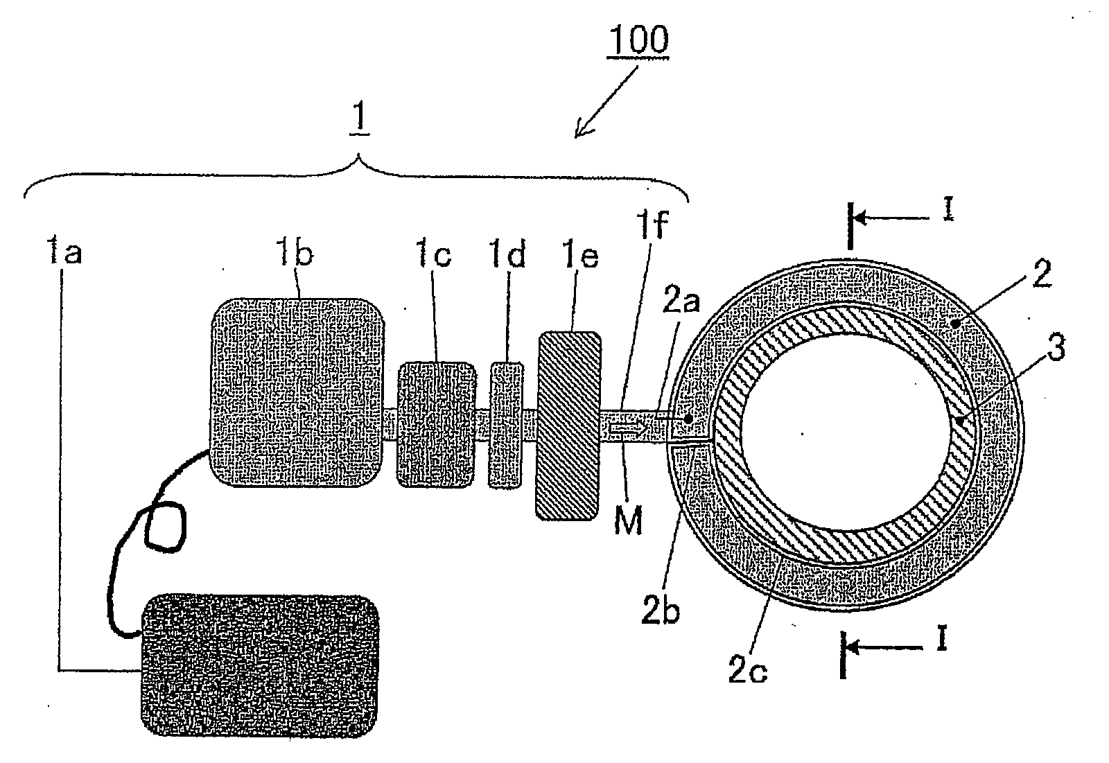
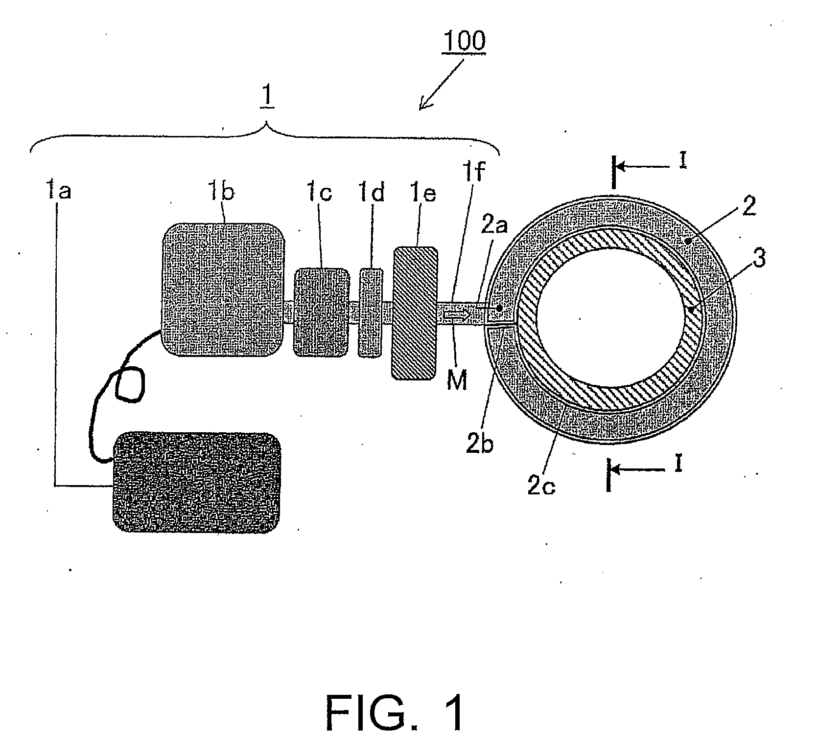
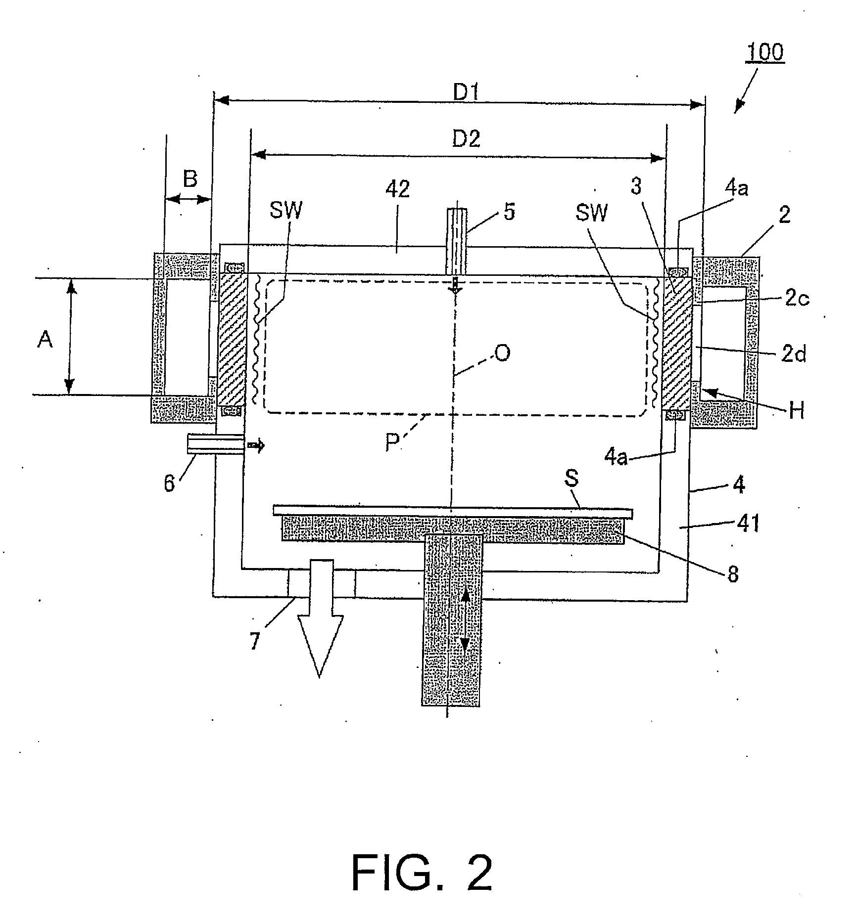
[0025]FIG. 1 is a schematic view of an overall structure of a SWP processing apparatus according to a first embodiment of the present invention. FIG. 2 is a cross-sectional view of the main parts of the SWP processing apparatus in FIG. 1 along the line of I-I. FIG. 3 is a horizontal cross-sectional view of the main parts of the SWP processing apparatus in FIG. 1.

[0026]Referring to FIGS. 1 and 2, the structure of the SWP processing apparatus 100 includes a SWP generator 10 and a plasma treatment chamber 4. The SWP generator 10 includes a microwave generator 1, an annular waveguide 2, and a dielectric tube 3. The annular waveguide 2 is connected with the microwave generator 1, and the dielectric tube 3 is disposed at an inner side of the annular waveguide 2. In the plasma treatment chamber 4, an upper surface gas inlet pipe 5, a side surface gas inlet pipe 6, a gas outlet 7, and a substrate holder 8 are disposed, wherein the upper surface gas inlet pipe 5 is used for introducing a pro...

second embodiment

[0044]In the first embodiment, the circumferential length of the annular waveguide 2 and the position of the slot antennas 2d are optimized with respect to the wavelength λg (or the constant k) in waveguide. In the second embodiment, the circumferential length of the inner surface of the dielectric tube 3 is optimized with respect to the wavelength of the surface wave SW propagating on the dielectric surface. Therefore, the basic structures of the SWP generator 10 and the SWP processing apparatus 100 in the second embodiment are the same as those in the first embodiment; Thus, in order to avoid being redundant, merely the differences with respect to the first embodiment are illustrated.

[0045]As described above, when the microwave M is introduced into the dielectric tube 3 from the annular waveguide 2 through the slot antennas 2d, the plasma P is generated within the inner space of the dielectric tube 3 by utilizing the energy of the surface wave SW formed on the inner peripheral sur...


PUM

PropertyMeasurementUnit
Distanceaaaaaaaaaa

Abstract

The present invention provides a surface wave excitation plasma generator in which surface wave excitation plasma is efficiently generated. A surface wave excitation plasma generator including an annular waveguide and a dielectric tube is provided. The annular waveguide 2 includes an inlet 2a for introducing a microwave M, an end plate 2b for reflecting the microwave M introduced and propagating within the waveguide, and a bottom plate 2c on which slot antennas 2d are formed at a predetermined interval. When the wavelength of the microwave M in the waveguide is λg, the length from position b through positions c, d, e to position f on the bottom plate 2c, i.e. the circumferential length (π×D1) of the annular waveguide, is set as 2 λg, and the positions b, c, d, e, f are spaced apart at an interval of λg/2. Since the slot antennas 2d are arranged at two positions c and e, the interval between these two slot antennas 2d is equal to the wavelength λg in the waveguide.

Description

CROSS-REFERENCE TO RELATED APPLICATION[0001]This application claims the priority benefit of Japanese application serial no. 2005-128079, filed Apr. 26, 2005. All disclosure of the Japanese application is incorporated herein by reference.BACKGROUND OF THE INVENTION[0002]1. Field of the Invention[0003]The present invention relates to a surface wave excitation plasma generator for generating surface wave excitation plasma by introducing microwave from a microwave generator, and a surface wave excitation plasma processing apparatus for performing chemical vapor deposition (CVD) or etching by utilizing the surface wave excitation plasma.[0004]2. Description of Related Art[0005]Surface wave plasma (SWP) is generated through the following ways. A microwave propagating in a microwave waveguide is introduced into a dielectric member through a slot antenna, and the plasma is excited by a surface wave generated on the surface of the dielectric member due to the microwave power to generate surf...

Claims


Application Information

Patent Timeline
IPC IPC(8): H01J7/24
CPCC23C16/511H05H1/46H01J37/32229H01J37/32192H01L21/205H01L21/3065
Inventor SUSUKI, MASAYASU
Owner SHIMADZU CORP
Why Eureka
Try Eureka