Drive unit, smoothing circuit, dc/dc converter

Active Publication Date: 2009-01-29
ROHM CO LTD
View PDF17 Cites 60 Cited by
  • Summary
  • Abstract
  • Description
  • Claims
  • Application Information

AI Technical Summary

Benefits of technology

[0009]In view of the problems described above, a first object of the present invention is to provide drive units that can control a load at lower driving levels with a high degree of accuracy; a second object is to provide smoothing circuits that can reduce the sound

Problems solved by technology

In addition, with respect to a DC/DC converter that converts an input voltage into a desired output voltage and feeds it to the load, the following problem arises.
If voltage variation appears in an input bypass capacitor which is an input smoother of the DC/DC converter or an output capacitor which i

Method used


Image

  • Drive unit, smoothing circuit, dc/dc converter
  • Drive unit, smoothing circuit, dc/dc converter
  • Drive unit, smoothing circuit, dc/dc converter

Examples


Embodiment Construction

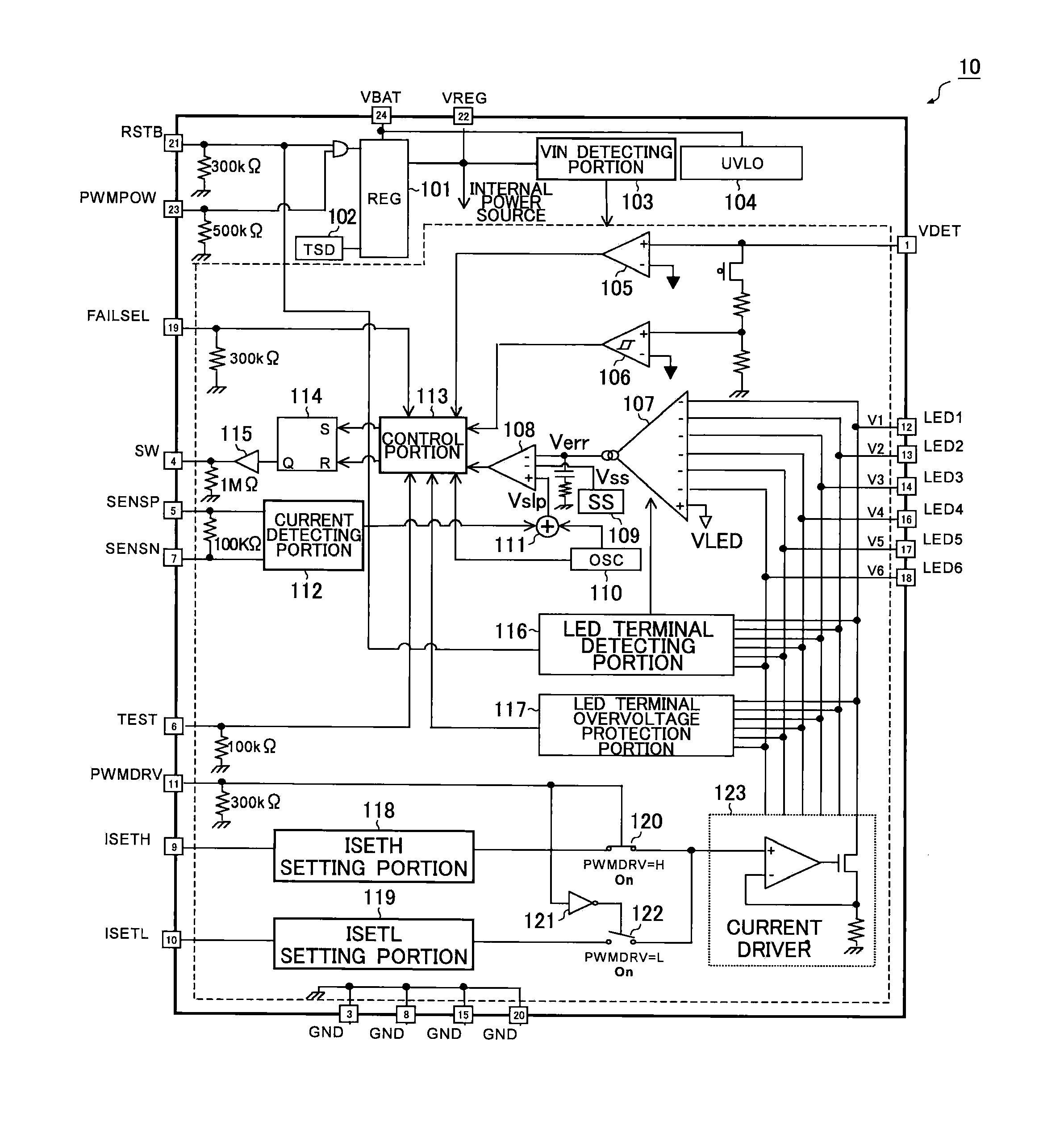
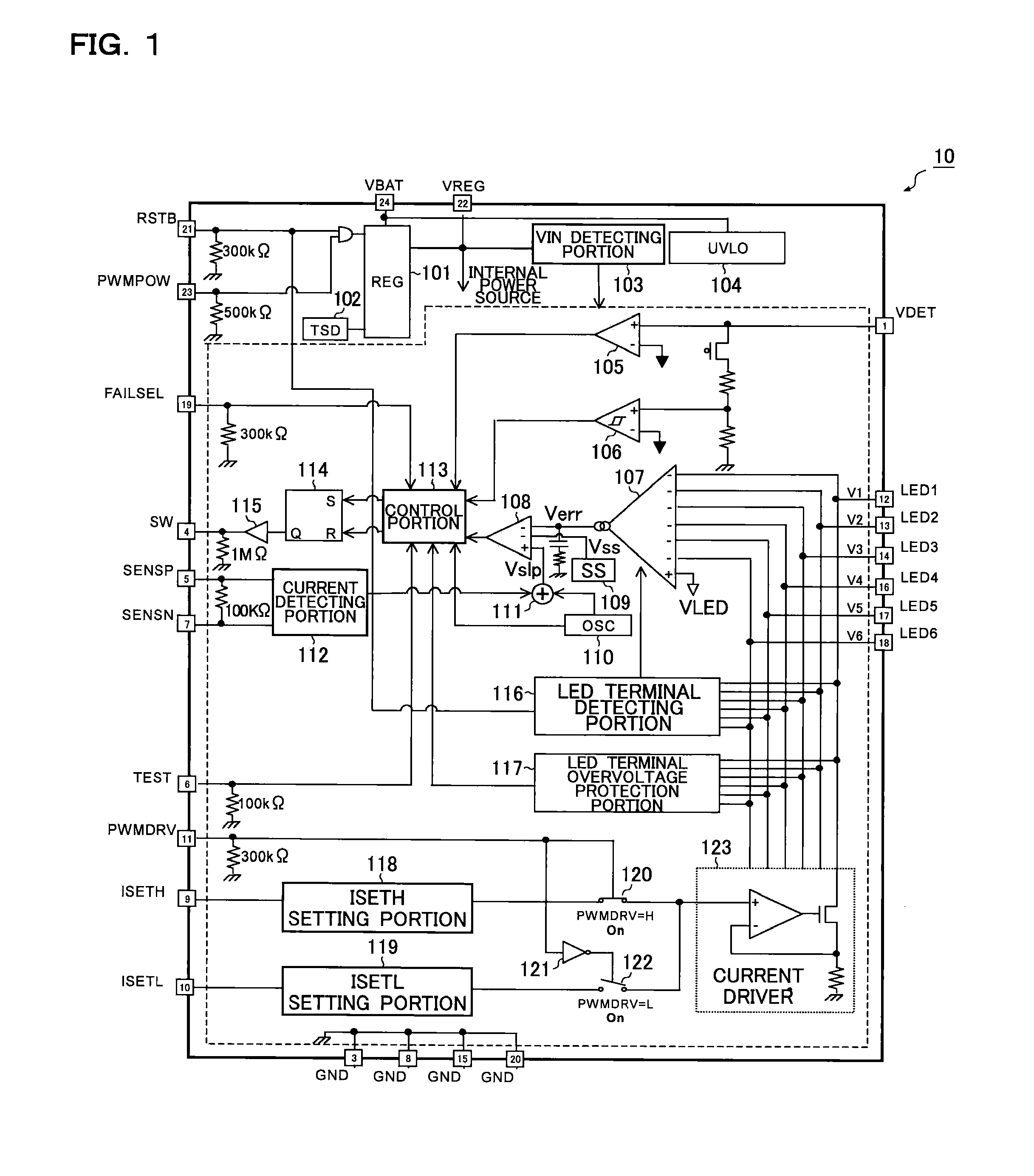
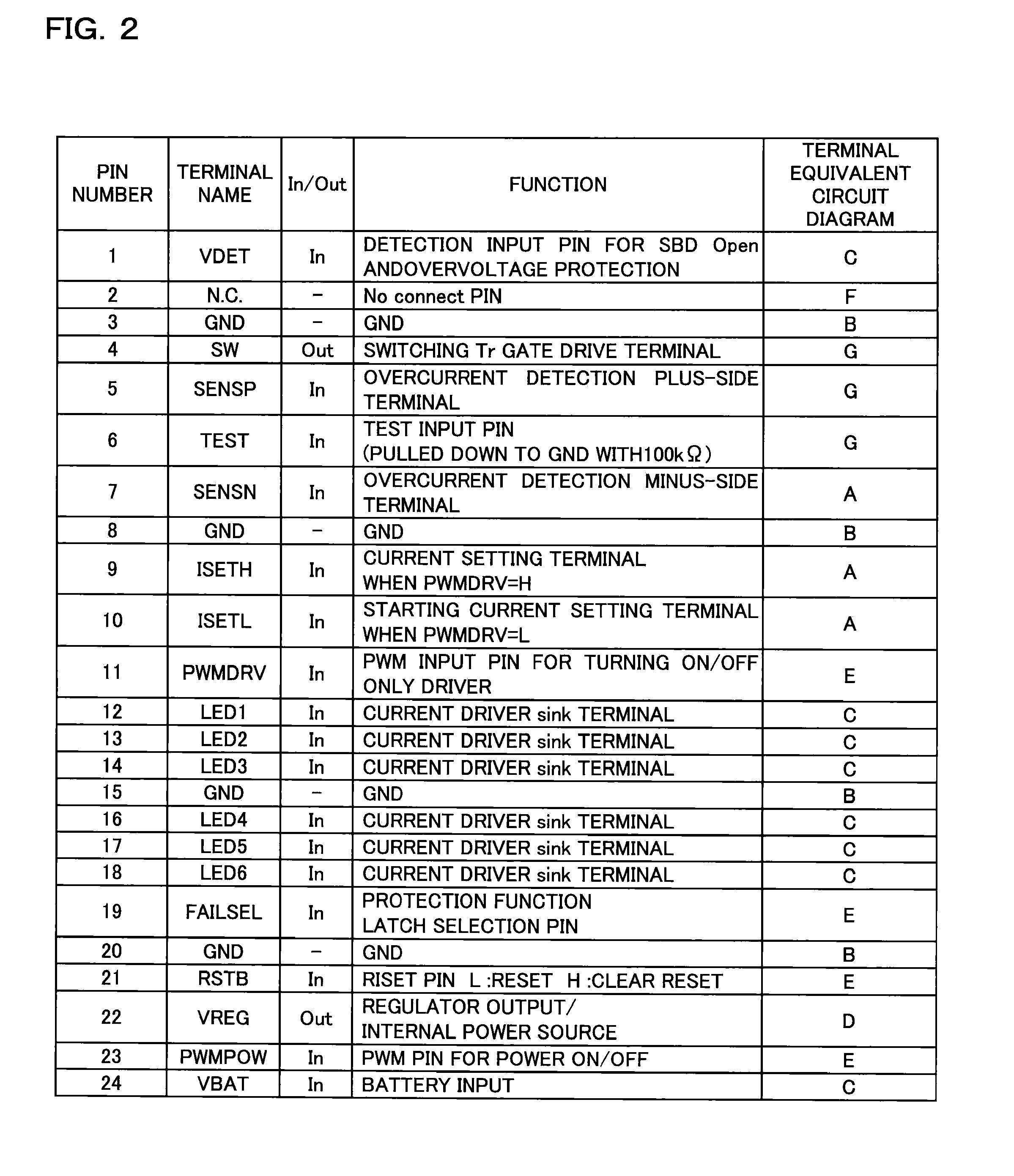
[0061]FIG. 1 is a block diagram showing a semiconductor device of an embodiment according to the present invention.

[0062]First, an outline of the semiconductor device 10 of this embodiment will be described.

[0063]The semiconductor device 10 of this embodiment shown in FIG. 1 is a white LED driver IC into which a DC / DC converter of PWM (pulse width modulation) type, the DC / DC converter that can step up a voltage up to 42.5 V, and a current driver that can drive LEDs at up to 25 mA are integrated. By controlling a power control terminal (PWMPOW terminal) of the IC or a power control terminal (PWMDRV terminal) of the current driver with a PWM signal fed from outside, it is possible to perform brightness control with high accuracy over a wide range. In addition, the adoption of a high-precision current driver helps reduce the error between lines, making it suitable to reduce variations in brightness of the display. Furthermore, the semiconductor device 10 adopts a compact package contri...


PUM


Abstract

A drive unit has a load driving portion driving a load by a PWM drive method; a soft-start function portion for achieving a soft-start function; and a soft-start disabling portion counting a time elapsed after a PWM signal is turned on at start-up of the unit, and disabling the soft-start function when a count value reaches a predetermined value.

Description

[0001]This application is based on Japanese Patent Applications Nos. 2007-194087 and 2007-336878 filed on Jul. 26, 2007 and Dec. 27, 2007 respectively, the contents of which are hereby incorporated by reference.BACKGROUND OF THE INVENTION[0002]1. Field of the Invention[0003]The present invention relates to drive units that control the driving of a load (such as a light-emitting diode). The present invention also relates to smoothing circuits that smooth an alternating-current signal by using an output capacitor connected in parallel with the load, and to DC / DC converters that convert an input voltage into a desired output voltage and feed it to the load.[0004]2. Description of Related Art[0005]Currently, as a backlight of an LCD (liquid crystal display) panel (for example, a monitor of a car navigation system), cold cathode fluorescent lamps (CCFL) are mainly used. In recent years, however, white LEDs (light-emitting diodes) have been put to practical use for their advantages such a...

Claims


Application Information

Patent Timeline
IPC IPC(8): H05B37/02G05F1/577H05B44/00
CPCH02M1/36H05B33/0803H05B33/0815H05B33/0818H05B33/0836H05B33/0842H05B33/089G05F3/08H05B33/0827H05B45/46H05B45/50H05B45/38H05B45/54H05B45/325
Inventor OMI, MASAKI
Owner ROHM CO LTD
Why Eureka
Try Eureka