Projection display apparatus

a display device and projection technology, applied in the field of projection display devices, can solve the problems of low work efficiency, huge time and effort required by users to perform input operations on the display screen, and achieve the effects of reducing misregistration, reducing misregistration, and improving user work efficiency

Inactive Publication Date: 2009-01-29
SONY CORP
View PDF12 Cites 6 Cited by
  • Summary
  • Abstract
  • Description
  • Claims
  • Application Information

AI Technical Summary

Benefits of technology

[0009]It is therefore desirable to provide a projection display apparatus realizing improvement in work efficiency of the user at the time of registration adjustment.
[0010]According to an embodiment of the present invention, there is provided a projection display apparatus including: a light source; a spatial light modulation device modulating, on the basis of a video signal, each of primary color lights for color display emitted from the light source; projecting means for projecting, onto a screen, each of the primary color lights modulated by the spatial light modulation device; and correcting means for correcting, based on a given correction value, the video signal for each of the primary color lights so as to reduce misregistration between the primary color lights projected on the screen, and supplying the corrected video signal to the spatial light modulation device. The correcting means is configured to correct the video signal according to a single correction value such that a group of correction target points selected in a projected image on the screen are collectively processed as a single correction unit.
[0011]In the projection display apparatus of the embodiment of the present invention, light emitted from the light source is modulated by the spatial light modulation device on the basis of a video signal for each of the primary color lights, and the modulated primary color lights are projected onto the screen, thereby displaying a video image based on the video signal. The video signals for each of the primary color lights are corrected so as to reduce the misregistration between the primary color lights projected on the screen, and the corrected video signals are supplied to the spatial light modulation device. Thus, occurrence of out-of-color-registration caused by the misregistration between the primary color lights is suppressed, and the display quality improves. The correcting means is configured to correct the video signal according to a single correction value such that a group of correction target points selected in a projected image on the screen are collectively processed as a single correction unit. Therefore, as compared with the technique of the related art of correcting correction points one by one, time necessary for the registration adjusting process is shortened.
[0012]In the projection display apparatus of the embodiment of the present invention, the video signals for each of the primary color lights are corrected so as to reduce the misregistration between primary color lights projected on a screen (registration adjustment is performed). Therefore, occurrence of out-of-color-registration caused by the misregistration between the primary color lights is suppressed, and the display quality is improved. At the time of correcting video signals, using a plurality of correction points in a display screen as a single object to be corrected, the video signals can be corrected concurrently according to a single correction value. The correcting means is configured to correct the video signal according to a single correction value such that a group of correction target points selected in a projected image on the screen are collectively processed as a single correction unit. Therefore, as compared with the technique of the related art of correcting correction points one by one, time necessary for the registration adjusting process is shortened. Thus, the work efficiency of the user at the time of registration adjustment may be improved.

Problems solved by technology

It is, therefore, very complicated for the user to perform an input operation on the display screen.
As a result, enormous time is necessary for the registration adjusting process as a whole, and the work efficiency is low.

Method used


Image

  • Projection display apparatus
  • Projection display apparatus
  • Projection display apparatus

Examples


Embodiment Construction

[0026]Embodiments of the present invention will be described in detail hereinbelow with reference to the drawings.

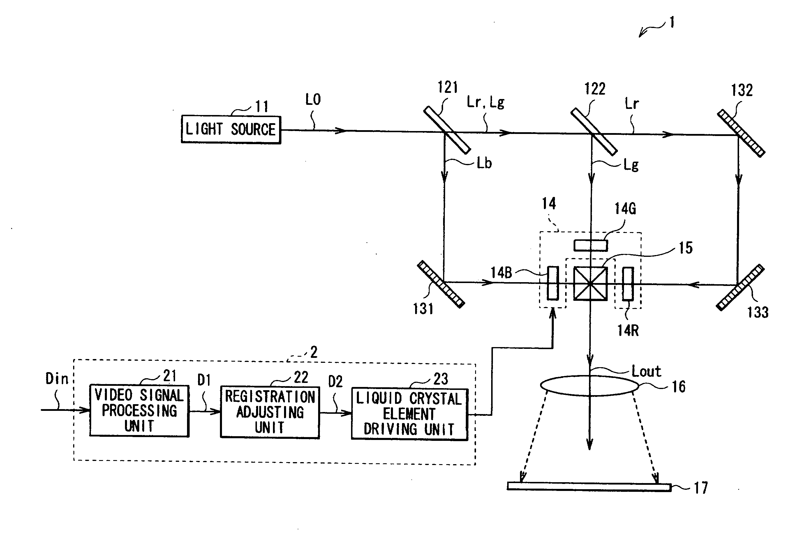
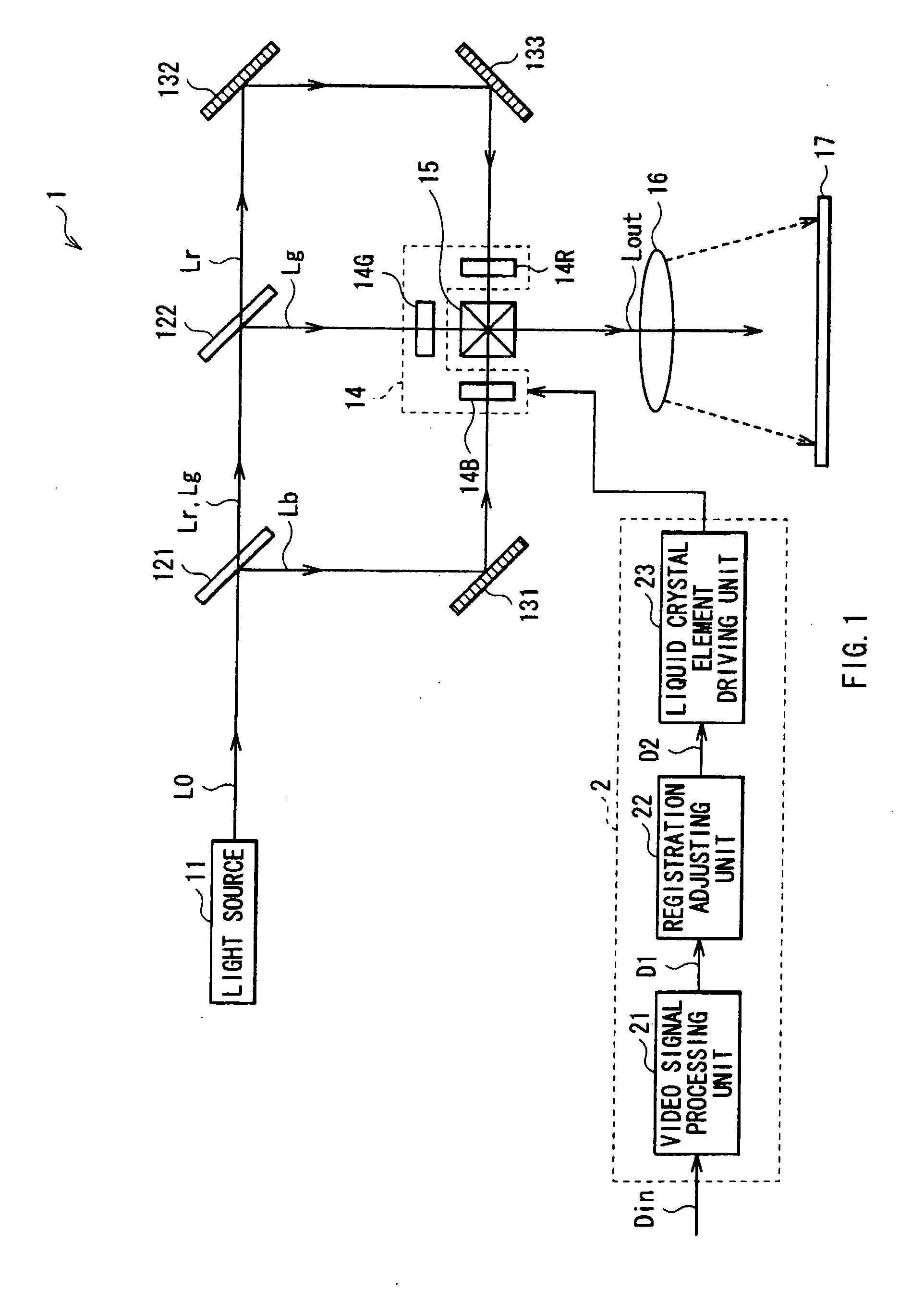
[0027]FIG. 1 shows a general configuration of a projection display apparatus (liquid crystal projector 1) as an embodiment of the present invention. The liquid crystal projector 1 displays a video image on the basis of an input video signal Din supplied from the outside. The liquid crystal projector 1 includes a light source 11, dichroic mirrors 121 and 122, reflection mirrors 131, 132, and 133, a light modulator 14, a dichroic prism 15, a projection lens 16, a screen 17, and a control unit 2 for controlling the light modulator 14 on the basis of the input video signal Din.

[0028]The light source 11 generates white light including primary color light of red light (R), blue light (B), and green light (G) which is necessary to display a color image. The light source 11 is configured by, for example, a halogen lamp, a metal halide lamp, a xenon lamp, or the like.

[0029]The di...


PUM


Abstract

A projection display apparatus includes: a light source; a spatial light modulation device modulating, on the basis of a video signal, each of primary color lights for color display emitted from the light source; projecting means for projecting, onto a screen, each of the primary color lights modulated by the spatial light modulation device; and correcting means for correcting, based on a given correction value, the video signal for each of the primary color lights so as to reduce misregistration between the primary color lights projected on the screen, and supplying the corrected video signal to the spatial light modulation device. The correcting means is configured to correct the video signal according to a single correction value such that a group of correction target points selected in a projected image on the screen are collectively processed as a single correction unit.

Description

CROSS REFERENCE TO RELATED APPLICATIONS[0001]The present invention contains subject matter related to Japanese Patent Application JP 2007-193791 filed in the Japanese Patent Office on Jul. 25, 2007, the entire contents of which being incorporated herein by reference.BACKGROUND OF THE INVENTION[0002]1. Field of the Invention[0003]The present invention relates to a projection display apparatus applied to a liquid crystal projector and the like.[0004]2. Description of the Related Art[0005]A projection display apparatus (for example, a liquid crystal projector) is being spread, which displays a picture by spatially modulating incident light on a spatial light modulation device in accordance with an electric signal applied to the spatial light modulation device, outputting the modulated light, and collecting and projecting the outgoing light. Such a projection display apparatus has generally a lamp as a light source, a condenser, and an illumination optical system for condensing light em...

Claims


Application Information

Patent Timeline
Patent Type & Authority Applications(United States)
IPC IPC(8): H04N9/31
CPCH04N9/3105H04N9/3197H04N9/3185
Inventor NISHIMURA, KOICHIROKONDO, YOSHITAKE
Owner SONY CORP
Why Eureka
Try Eureka