Beaconless adaptive optics system

a beamless adaptive and optics technology, applied in the field of beamless adaptive optics systems, can solve the problems of reducing the flux to harmless levels, not providing a light source that could serve as a beam, and other in line light sources may not be available, and achieve the effect of high speed control

Inactive Publication Date: 2009-01-29
TREX ENTERPRISES CORP
View PDF0 Cites 23 Cited by
  • Summary
  • Abstract
  • Description
  • Claims
  • Application Information

AI Technical Summary

Benefits of technology

[0025]The present invention provides an improved beaconless adaptive optics system and process. A target is illuminated with a high energy laser beam of a directed energy laser. Wave front measurements are made of high energy laser beam reflections from the target. These wave front measurements are analyzed by a high speed processor to determine both high frequency phase components and low frequency phase components in the wave front data. (Applicants' experiments have shown that there is a direct correlation between beam spot size on the target and the phase variance of the reflected laser beam. The correlation is: the greater the phase variance the smaller the beam spot size.) Applicants have developed a technique for providing special control algorithms that provide very high speed control of the elements of a deformable mirror using this phase variance as a feedback parameter. Applicants have also developed algorithms to correct a limited number of Zernike modes associated with the wave front control.

Problems solved by technology

However, depositing lethal flux on the target over sufficient time requires mitigation of the atmospheric turbulence effects on a laser beam.
This is because atmospheric turbulence produces distortions that tend to spread out the laser beam to increase the spot size on the target, reducing the flux to harmless levels.
However, most non cooperative targets would not provide a light source that could serve as a beacon and other in line light sources may not be available.
However, since light reflected from the target propagates back to the laser platform through turbulence and thermal blooming, both thermal blooming and turbulence degrade the beacon image and thus limit the sensitivity of the performance metric to the variations of the HEL beam spot size at the target.
So, the imaging system may not be able to resolve small variations of the beam spot size at the target at each iteration of the optimization algorithm.

Method used


Image

  • Beaconless adaptive optics system
  • Beaconless adaptive optics system
  • Beaconless adaptive optics system

Examples


Embodiment Construction

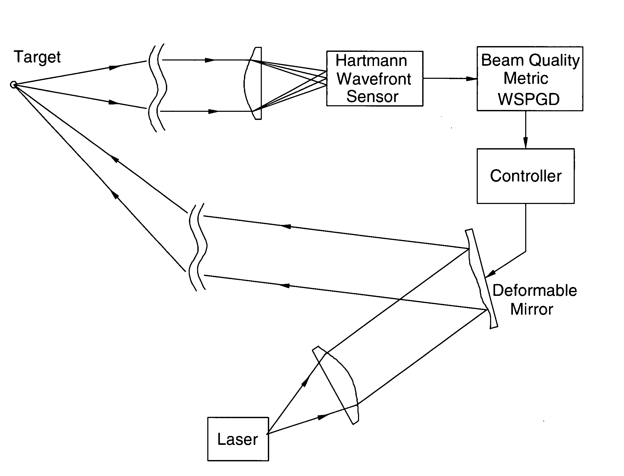
[0033]A first preferred embodiment of the present invention provides a beam control approach somewhat similar to the approached pioneered by M. Vorontsov and others that is discussed in the background section of this specification. Applicants have introduced a concept of a Wavefront-based Stochastic Parallel Gradient Decent (WSPGD) adaptive optics system, which uses off-axis wavefront measurements of laser return to provide feedback for an optimization algorithm. Applicants have validated this concept in simulation using a wave-optics code. The WSPGD adaptive optics system concept is based on three findings:[0034]the phase aberrations of laser return from the target contain information about beam spot size at the target;[0035]the variance of differential local wavefront tilt depends inversely proportional on beam spot size at the target; and[0036]correction of a limited number of low-order Zernike modes significantly increases on-axis intensity and power in the bucket at the target....


PUM


Abstract

An improved beaconless adaptive optics system and process. A target is illuminated with a high energy laser beam of a directed energy laser. Wave front measurements are made of high energy laser beam reflections from the target. These wave front measurements are analyzed by a high speed processor to determine both high frequency phase components and low frequency phase components in the wave front data. (Applicants' experiments have shown that there is a direct correlation between beam spot size on the target and the phase variance of the reflected laser beam. The correlation is: the greater the phase variance the smaller the beam spot size.) Applicants have developed a technique for providing special control algorithms that provide very high speed control of the elements of a deformable mirror using this phase variance as a feedback parameter. Applicants have also developed algorithms to correct a limited number of Zernike modes associated with the wave front control.

Description

CROSS REFERENCE TO RELATED APPLICATIONS[0001]This application claims the benefit of provisional patent application Ser. No. 60 / 933,603 filed Jun. 6, 2008.FEDERAL SPONSORED RESEARCH[0002]The present invention was made in the course of performance of Contract Nos. FA9451-06-D-0006 and FA9451-04-C-0321 with the United States Air Force and the United States Government has rights in the invention.FIELD OF INVENTION[0003]The present invention relates to imaging and laser projection systems and in particular to such systems involving turbulence.BACKGROUND OF THE INVENTIONDirected Energy Systems[0004]Since the invention of the laser, consideration has been given to development of directed energy systems. These systems require techniques to maximize the laser power density on the target. This means the laser “spot size” on the target must be as small as possible. Recent progress in high power laser technology makes these systems feasible. However, depositing lethal flux on the target over su...

Claims


Application Information

Patent Timeline
Patent Type & Authority Applications(United States)
IPC IPC(8): H01S3/00
CPCG02B27/52
Inventor BELENKII, MIKHAIL
Owner TREX ENTERPRISES CORP
Why Eureka
Try Eureka