
Lubricant coater, image bearing unit, and image forming apparatus

a technology of image bearing and lubricant coater, which is applied in the direction of electrographic process apparatus, instruments, optics, etc., can solve the problem of fine streaks on images

Inactive Publication Date: 2009-01-29
RICOH KK
View PDF11 Cites 26 Cited by
  • Summary
  • Abstract
  • Description
  • Claims
  • Application Information

AI Technical Summary

Benefits of technology

[0015]Further, excellent lubrication property can be maintained for a long period of time. Furthermore, a surface of an image bearing member can be favorably protected from stress caused by electrostatic discharge by forming a film composed of the powder on the surface of the image bearing member.
[0017]The inventors have diligently examined the cause of these fine streaks and found out that a relatively thicker portion of the film of the lubricant formed on a surface of an image bearing member prevents exposure to the image bearing member to cause such a formation defect of the latent electrostatic image.
[0018]The present invention has been made in view of the above-mentioned background. An object of the present invention is to provide the following lubricant coater and image forming apparatus. Specifically, provided are a lubricant coater and an image forming apparatus which are capable of maintaining excellent lubrication property between an image bearing member and a cleaning member for a long period of time, efficiently protecting the surface of the image bearing member from stress caused by electrostatic discharge, and preventing the occurrence of fine-streaky images caused by defective exposure of the image bearing member.
[0041]In the lubricant coater of the present invention, as a powder of lubricant or a lubricant in powder form, a powder of lubricant containing paraffin as a main component is used. With this setting, as is clarified by the experiments made by the inventors, which will be described hereinafter, it is possible to maintain excellent lubrication property between an image bearing member and a cleaning member for a long period of time and to efficiently protect the surface of the image bearing member from stress caused by electrostatic discharge.
[0042]Further, as is clarified by the experiments made by the inventors, which will be described hereinafter, it is possible to prevent the occurrence of fine-streaky images caused by defective exposure of an image bearing member by controlling a maximum thickness of a lubricant film formed on a surface of an image bearing member, which is obtained when the lubricant powder is continuously applied for 120 minutes, so as to be 0.25 μm or less.

Problems solved by technology

However, when this lubricant is used, fine streaks sometimes occur on an image.

Method used


Image

  • Lubricant coater, image bearing unit, and image forming apparatus
  • Lubricant coater, image bearing unit, and image forming apparatus
  • Lubricant coater, image bearing unit, and image forming apparatus

Examples


examples

[0211]Hereafter, the present invention will be further described in detail referring to specific Examples, however, the present invention is not limited to the disclosed Examples. On the contrary, the present invention is intended to cover various modifications and equivalent arrangements included within the spirit and scope of the appended claims.

experiment 1

[Experiment 1]

[0212]The inventors produced 21 samples of solid lubricants of Sample Nos. (1) to (21) as follows. Firstly, the components shown in Table 1 were put in a glass vessel with a lid. The components were agitated and melted with a hot stirrer under a predetermined temperature condition (the melting point shown in Table 2) to obtain a melt. Next, an aluminum die with an inside size of 12 mm×8 mm×350 mm was heated to the pre-heating temperature shown in Table 2. The melt was poured into the heated die and then naturally cooled down to a first cooling temperature (shown in Table 2). Next, the die was placed in a thermostatic bath, heated again to a reheating temperature (shown in Table 2), left intact under the temperature for a predetermined time (re-heating time shown in Table 2) and then naturally cooled down to the final cooling temperature shown in Table 2. A solid matter of lubricant obtained by the standing to cool was taken out from the die, and cut-formed in 7 mm×8 mm...

experiment 2

[Experiment 2]

[0222]Firstly, a solid lubricant was produced as follows. A normal paraffin having a melting point of 104° C. (79 parts by mass), a normal paraffin having a melting point of 112° C. (10 parts by mass) and 11 parts by mass of a cyclic polyolefin having a melting point of 60° C. (TOPAS-TM available from Ticona Co.) were put in a glass vessel with a lid. The components were agitated and melted with a hot stirrer at a temperature of 125° C. to obtain a melt. Next, an aluminum die with an inside size of 12 mm×8 mm×350 mm was heated to 88° C. The melt was poured into the heated die and then naturally cooled down to 50° C. Next, the die was placed in a thermostatic bath, heated again to 60° C., left intact under the temperature for 20 minutes and then naturally cooled down to the room temperature. A solid matter of lubricant obtained by the standing to cool was taken out from the die, and cut-formed in 7 mm×8 mm×310 mm, thereby obtaining a solid lubricant sample.

[0223]As a te...


PUM


Abstract

The present invention provides a lubricant coater including an applying member for applying a lubricant powder on a surface of an image bearing member, wherein the lubricant powder contains paraffin as a main component, and the lubricant coatability of the applying member is controlled such that a maximum thickness of a lubricant film formed on the image bearing member, which is obtained after the lubricant powder is continuously applied on the surface of the image bearing member for 120 minutes, is 0.25 μm or less.

Description

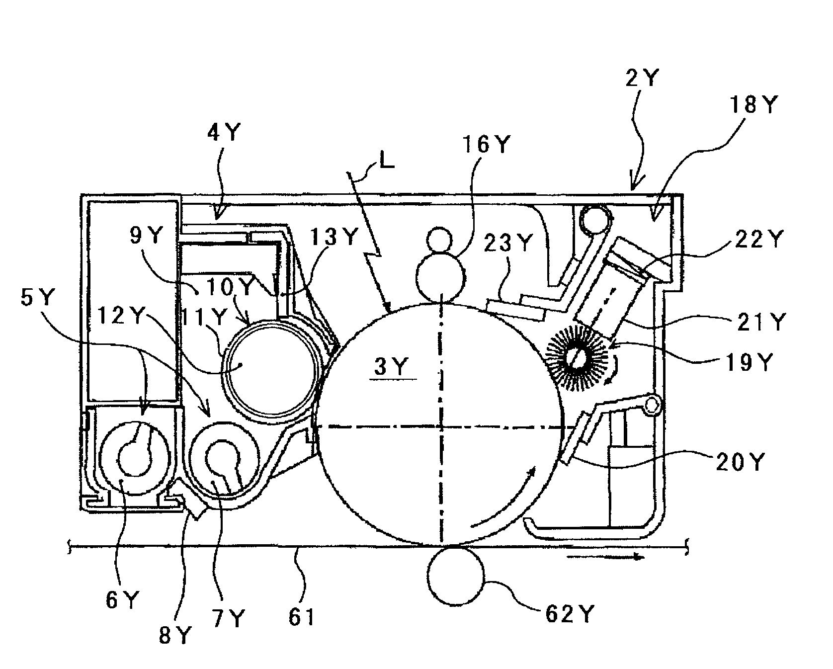
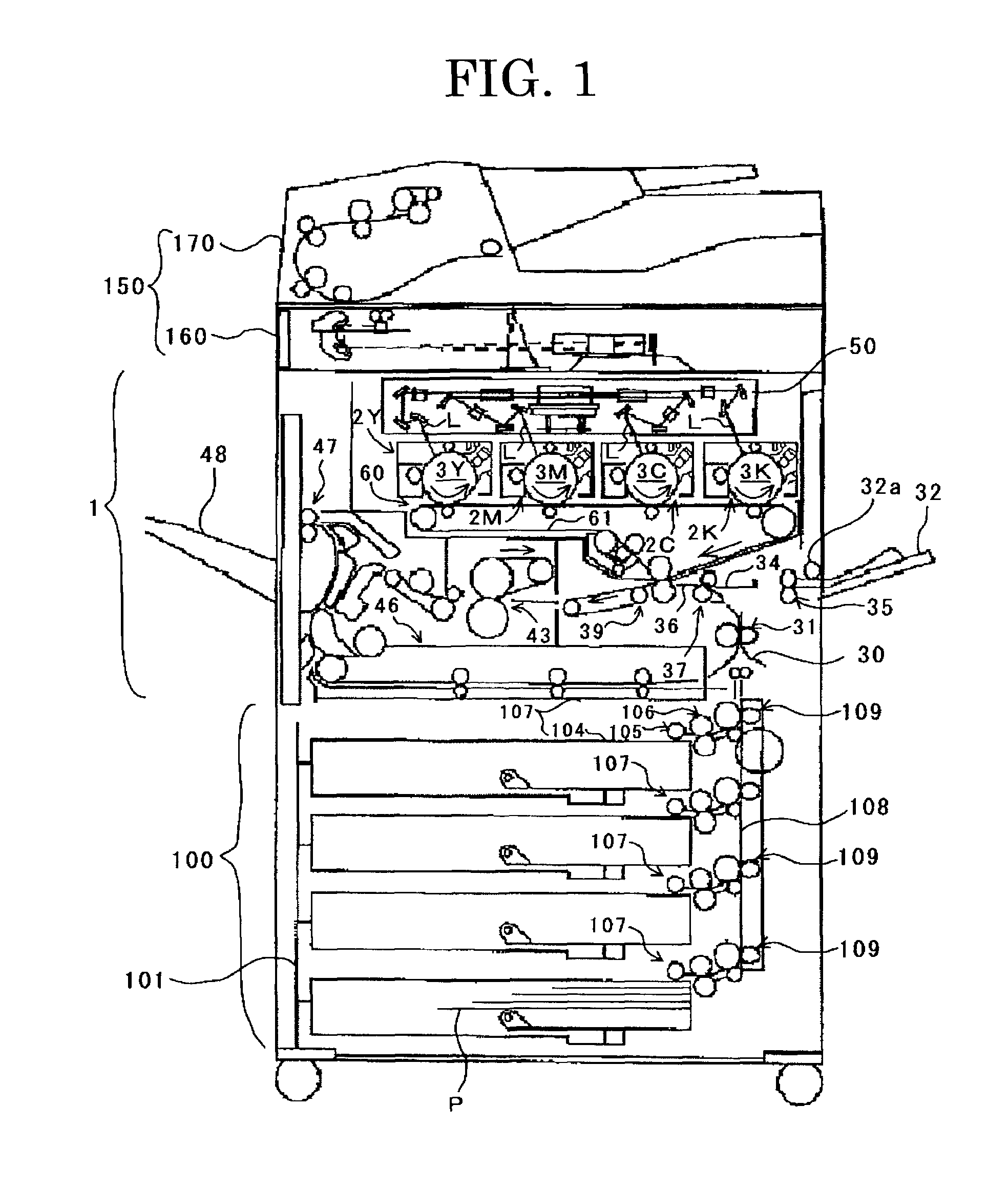
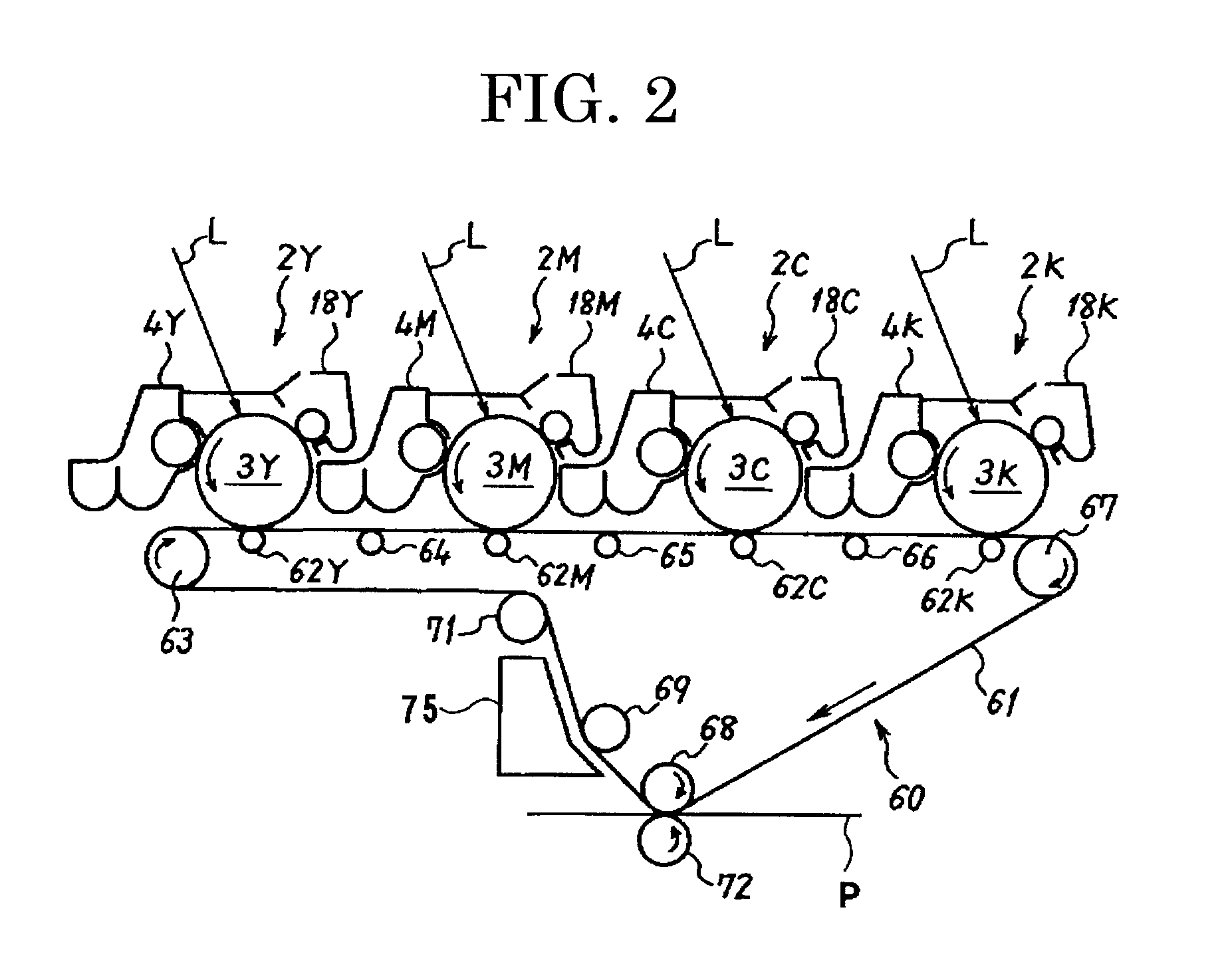
BACKGROUND OF THE INVENTION[0001]1. Field of the Invention[0002]The present invention relates to a lubricant coater for applying a lubricant on a surface of an image bearing member such as photoconductor, also relates to an image bearing unit using the lubricant coater, and an image forming apparatus using the lubricant coater.[0003]2. Description of the Related Art[0004]An electrophotographic image forming apparatus generally forms an image according to the following process. Firstly, an image bearing member such as photoconductor whose surface has been uniformly charged by a charging device is subjected to laser scanning to form a latent electrostatic image, and the latent electrostatic image is developed by a developing device to form a toner image. Subsequently, a toner image obtained by the developing step is directly transferred onto a recording medium such as transfer paper from the image bearing member or transferred onto recording paper via an intermediate transfer member. ...

Claims


Application Information

Patent Timeline
Patent Type & Authority Applications(United States)
IPC IPC(8): G03G21/00
CPCG03G2221/0084G03G21/0011
Inventor KABATA, TOSHIYUKIHATAKEYAMA, KUMIKOYAMASHITA, MASAHIDE
Owner RICOH KK
Learn More