Wind turbine rotor blade and pitch regulated wind turbine

Inactive Publication Date: 2009-01-29
SIEMENS AG
View PDF3 Cites 15 Cited by
  • Summary
  • Abstract
  • Description
  • Claims
  • Application Information

AI Technical Summary

Benefits of technology

[0011]As has already been mentioned in the introduction stall inducing devices on the leading edge or at the downwind side of a wind turbine rotor blade airfoil profile are already known from stall regulates wind turbines. In these cases the stall inducing devices are used to reduce the positive lift and thereby reduce the active power of a wind turbine. However, stall inducing devices on the upwind side of a wind turbine blade airfoil profile have different effects compared to the stall inducing devices at the leading edge or downwind side for power regulation in stall regulated wind turbines. By situating such stall inducing devices at the upwind side in pitch regulated wind turbines the maximum negative lift on the airfoil is reduced by disturbing the flow at the upwind side.
[0013]A wind turbine operates in a turbulent wind field. This results in a different angle of attack of the relative wind at a given pitch angle as measured with respect to the chord of the profile. Different angles of attack, however, lead to different lifts on the airfoil. For usual operation conditions at moderate turbulence a pitch regulated turbine always operates in a linear part of the lift curve, i.e. the lift changes proportional to a change in the angle of attack. In some situations, however, a combination of rotor position and a strong shear in the wind field may result in an angle of attack outside this linear region. In these situations the loads on the turbine will be strongly related to the maximum lift and the minimum lift of the airfoil. Both the minimum and the maximum lift are achieved just before the airfoil stalls. In the situation with negative lift the flow separates on the upstream side of the airfoil. Therefore, by changing the absolute value of the minimum lift of an airfoil would decrease both the fatigue and the extreme loads on the turbine.
[0015]The stall inducing device of the inventive wind turbine rotor blade has the advantage of reducing the absolute value of the maximum negative lift but does not, to any appreciable degree, influence the operation characteristics of the blade profile in normal operation conditions. On the other hand, under operating conditions that can lead to a highly asymmetric loading it has a profound and positive influence on the loads.
[0016]An inventive pitch regulated wind turbine comprises a rotor with at least one inventive wind turbine rotor blade. In such a wind turbine the yawing and tilting moments on the wind turbine structure at high wind speeds can be reduced compared to a wind turbine without an inventive rotor blade.

Problems solved by technology

However, wind turbines usually operate in a turbulent wind field.
A pitch regulated wind turbine operating in such a turbulent wind field at high wind speed may experience negative lift on a part of the rotor blade's airfoil.

Method used


Image

  • Wind turbine rotor blade and pitch regulated wind turbine
  • Wind turbine rotor blade and pitch regulated wind turbine
  • Wind turbine rotor blade and pitch regulated wind turbine

Examples


Embodiment Construction

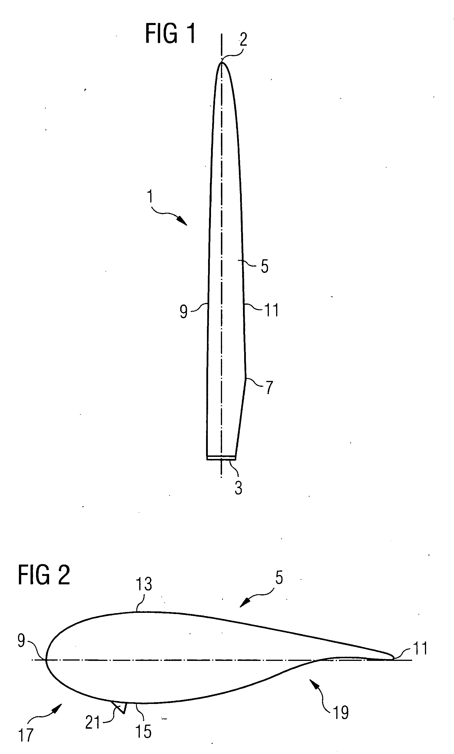
[0023]FIG. 1 shows a wind turbine blade 1 as it is usually used in a three-blade rotor. However, the present invention shall not be limited to blades for three-blade rotors. In fact, it may also be implemented in other rotors like one-blade rotors or two-blade rotors, or in rotors with more than three blades.

[0024]The rotor blade 1 shown in FIG. 1 comprises a root portion 3 with a cylindrical profile and a tip 2 which forms the outermost part of the blade 1. The cylindrical profile of the root portion 3 serves to fix the blade 1 to a bearing of a rotor hub (not shown). The rotor blade 1 further comprises a so-called shoulder 7 which is defined as being the location of the blades maximum profile depth, i.e. its maximum chord length. The airfoil 5 extends along the so-called span (dash dotted line in FIG. 1) between the root portion 3 and the tip 2.

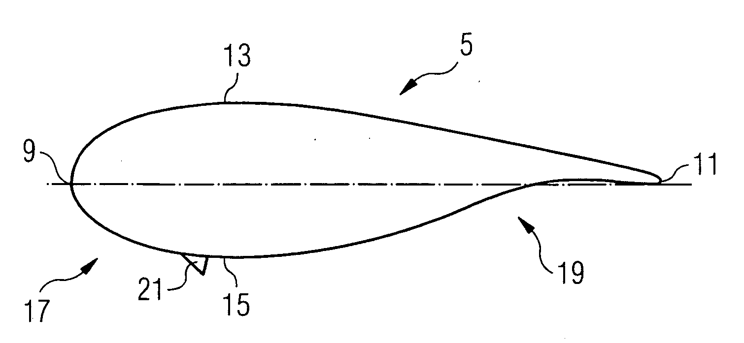
[0025]A chord-wise cross-section through the rotor blade's airfoil 5 is shown in FIG. 2. The aerodynamic profile of the airfoil 5 shown in...


PUM


Abstract

A wind turbine rotor blade with an airfoil profile having an upwind side, a downwind side is provided. A stall inducing device is located at the upwind side of the airfoil profile.

Description

CROSS REFERENCE TO RELATED APPLICATIONS[0001]This application claims priority of European Patent Office application No. 07014329.2 EP filed Jul. 20, 2007, which is incorporated by reference herein in its entirety.FIELD OF INVENTION[0002]The present invention relates to a wind turbine rotor blade and to a pitch regulated wind turbine comprising a rotor with at least one rotor blade.SUMMARY OF INVENTION[0003]There are two different ways of regulating the power output of a wind turbine, namely pitch regulation and stall regulation.[0004]In pitch regulated wind turbines the wind turbine power is regulated by setting an appropriate pitch angle for the rotor blades of the rotor. By setting the pitch angle, the machine can be operated with the optimum rotor speed in a wide range of wind speeds. However, wind turbines usually operate in a turbulent wind field. A pitch regulated wind turbine operating in such a turbulent wind field at high wind speed may experience negative lift on a part of...

Claims


Application Information

Patent Timeline
IPC IPC(8): F01D5/14F03D11/00
CPCF03D1/0641F03D7/0224F05B2240/30Y02E10/723F05B2250/11Y02E10/721F05B2240/32Y02E10/72
Inventor ENEVOLDSEN, PEDER BAYHJORT, SORENLAURSEN, JESPERNIELSEN, ANDERS VANGSGAARDRUBAK, RUNE
Owner SIEMENS AG
Why Eureka
Try Eureka