Hydrated EGR system, method and apparatus for reducing harmful exhaust emissions and improving fuel economy

a technology of hydrated egr and exhaust, which is applied in the direction of mechanical equipment, machines/engines, and non-fuel substance addition to fuel, etc., can solve the problems that the water-addition method including the egr process is not widely practiced in the engine system, and achieves the effects of improving engine performance, reducing harmful exhaust emissions, and improving fuel economy

Active Publication Date: 2009-02-05
RIM JULIUS J
View PDF27 Cites 11 Cited by
  • Summary
  • Abstract
  • Description
  • Claims
  • Application Information

AI Technical Summary

Benefits of technology

[0013]The hydrated EGR mixture is then fed back to an intake portion of the engine, is mixed with an incoming fuel / air mixture, and is burned with the fuel air mixture inside the engine. The use of the hydrated EGR mixture, including heated water vapor, as part of the intake charge simultaneously reduces harmful exhaust emissions, improves engine performance, and improves fuel economy of the vehicle.
[0014]The system according to the invention may incorporate a water tank that cooperates with the exhaust system to generate hydrated EGR, and then feeds such hydrated EGR into the intake manifold to be mixed with the air-fuel mixture entering the intake manifold, to improve fuel efficiency and increase engine power. The present invention also relates to a method of using such a water tank on a vehicle for treating exhaust from the vehicle's engine.
[0015]The emissions-reduction system according to the present invention also provides an optional method of supplying water vapor and a catalyst to a engine's intake manifold, via the EGR system, to reduce NOx formation from exhaust gases, without causing an engine wear problem, while improving fuel efficiency and increasing engine power.

Problems solved by technology

However, water-addition methods including the EGR process are not widely practiced in engine systems, partly because of concerns about possible engine wear problems caused by the potential break-down of the protective film of lubricating oil by contact with water in critical rubbing metal surfaces, such as the surfaces between piston rings and cylinder walls and valve bearings, etc.

Method used


Image

  • Hydrated EGR system, method and apparatus for reducing harmful exhaust emissions and improving fuel economy
  • Hydrated EGR system, method and apparatus for reducing harmful exhaust emissions and improving fuel economy
  • Hydrated EGR system, method and apparatus for reducing harmful exhaust emissions and improving fuel economy

Examples


Embodiment Construction

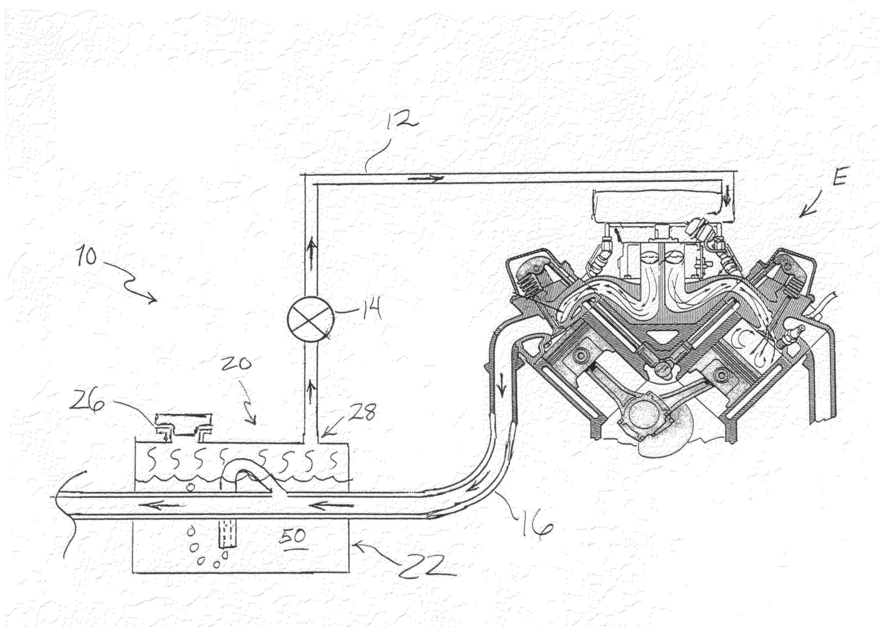
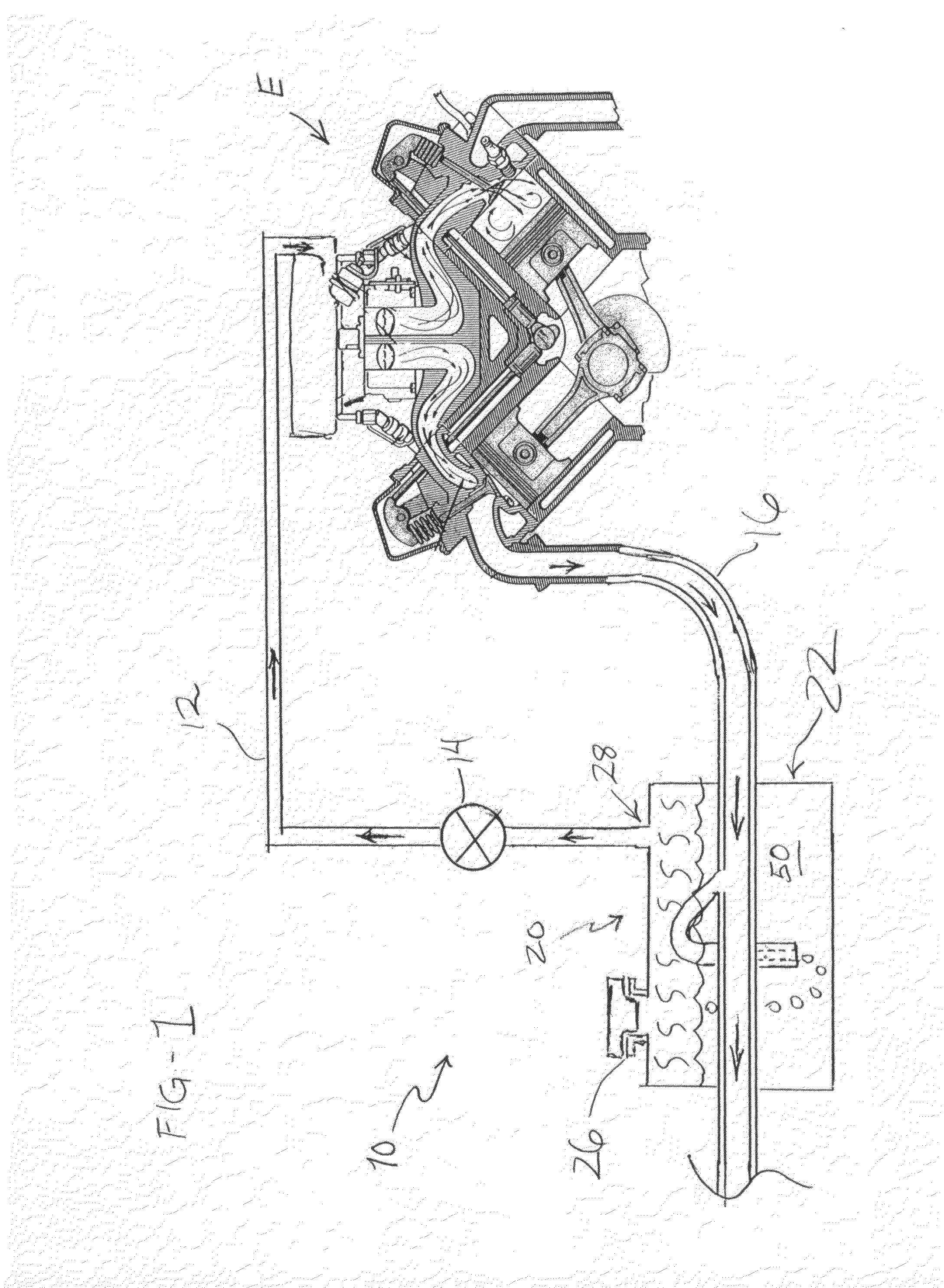
[0022]Referring now to FIG. 1 of the drawings, a hydrated EGR system according to an illustrative embodiment of the invention is shown generally at 10, for use with an internal combustion engine E. It will be understood that the emissions reducing system 10 according to the present invention is intended to be installed on a vehicle (not shown).

[0023]The emissions reducing system 10 according to the present invention is provided for use on an engine E, as shown schematically in the drawing. The core mechanical components of the engine E operate conventionally, using commercially available fuel in a fuel tank (not shown), which may be either diesel fuel or normal unleaded gasoline, depending on the type of engine used. As desired, the fuel may or may not be treated with a catalyst, and may be made up entirely of commercial fuel from a filling station. The engine E draws in air for combustion through its intake manifold 15.

[0024]The emissions reducing system 10 also includes an electro...


PUM


Abstract

A hydrated EGR system, method and apparatus for a vehicle, in which heat from an exhaust pipe is used to heat an aqueous fluid solution in a water tank. A portion of the hot exhaust gas is diverted from the main exhaust flow, and the diverted portion is bubbled through the heated aqueous fluid solution to form a hydrated EGR mixture containing water vapor. The hydrated EGR mixture is then fed back to an intake portion of the engine, is mixed with an incoming fuel/air mixture, and is burned with the fuel air mixture inside the engine. The use of the hydrated EGR mixture, including heated water vapor, as part of the intake charge simultaneously reduces harmful exhaust emissions, improves engine performance, and improves fuel economy of the vehicle.

Description

BACKGROUND OF THE INVENTION[0001]1. Field of the Invention[0002]The present invention relates to an hydrated EGR system, method and exhaust treatment apparatus for use in a vehicle having an internal combustion engine, to simultaneously reduce harmful exhaust emissions, improve engine performance and increase fuel economy. More specifically, the present invention relate to a hydrated EGR system, method and exhaust treatment apparatus in which heat from an exhaust pipe heats an aqueous fluid solution in a tank, and a portion of hot exhaust gas is bubbled through the heated aqueous fluid solution to form a hydrated EGR mixture containing water vapor. The hydrated EGR mixture is then fed to an intake portion of the engine, using pressure from the exhaust system, and the hydrated EGR mixture is burned with the air / fuel mixture as part of the combustion charge.[0003]2. Description of the Background Art[0004]In efforts to reduce global-warming gas emissions, energy-efficient internal comb...

Claims


Application Information

Patent Timeline
Patent Type & Authority Applications(United States)
IPC IPC(8): F02M25/07F01N3/04F02B47/08F01N13/12
CPCF01N5/02F02B47/08Y02T10/16Y02T10/121F02M25/0742F02M26/36Y02T10/12
Inventor RIM, JULIUS J.
Owner RIM JULIUS J
Why Eureka
Try Eureka