Gas Pressure Intensifier System for use with a Ventilator or Resuscitator

a gas pressure intensifier and ventilator technology, which is applied in the direction of respirator, operating means/releasing devices of valves, therapy, etc., can solve the problems of no known pressure intensifier system, reduce component operating temperature and gas stream temperature, reduce the temperature of high pressure gas stream, and reduce the operating temperature and pressure of chemical oxygen generating sources

Inactive Publication Date: 2009-02-05
KLEINBECK THOMAS RAYMOND
View PDF5 Cites 8 Cited by
  • Summary
  • Abstract
  • Description
  • Claims
  • Application Information

AI Technical Summary

Benefits of technology

[0011]It is the object of this invention to provide a method of delivering oxygen at sufficient pressure, with a sufficiently low dew point in the high pressure gas stream, to operate commercial off the shelf field transportable, emergency, or purpose designed ventilators or resuscitators, in a safe and stable manner. An example of a ventilator that can use two gas sources is the Smiths Medical, England, “Pneupac” product. This invention could be incorporated into the design of a single patient ventilator or as a stand alone unit. The invention uses a pressure intensifier to produce a high pressure gas stream and a low pressure gas stream from an intermediate pressure source. The invention may use a heat exchanger to reduce the temperature of the high pressure gas stream. The invention uses a desiccant such as lithium hydroxide, a molecular sieve, or a chemical reaction to remove water from the gas streams. This invention reduces the operating temperature and pressure of a chemical oxygen generating source used to power a pneumatic logic controlled ventilator or resuscitator. Other heat exchangers may be added to the system to reduce component operating temperatures and gas stream temperatures.

Problems solved by technology

No known pressure intensifier system is designed to use both exiting gas streams in a process.

Method used


Image

  • Gas Pressure Intensifier System for use with a Ventilator or Resuscitator
  • Gas Pressure Intensifier System for use with a Ventilator or Resuscitator
  • Gas Pressure Intensifier System for use with a Ventilator or Resuscitator

Examples


Embodiment Construction

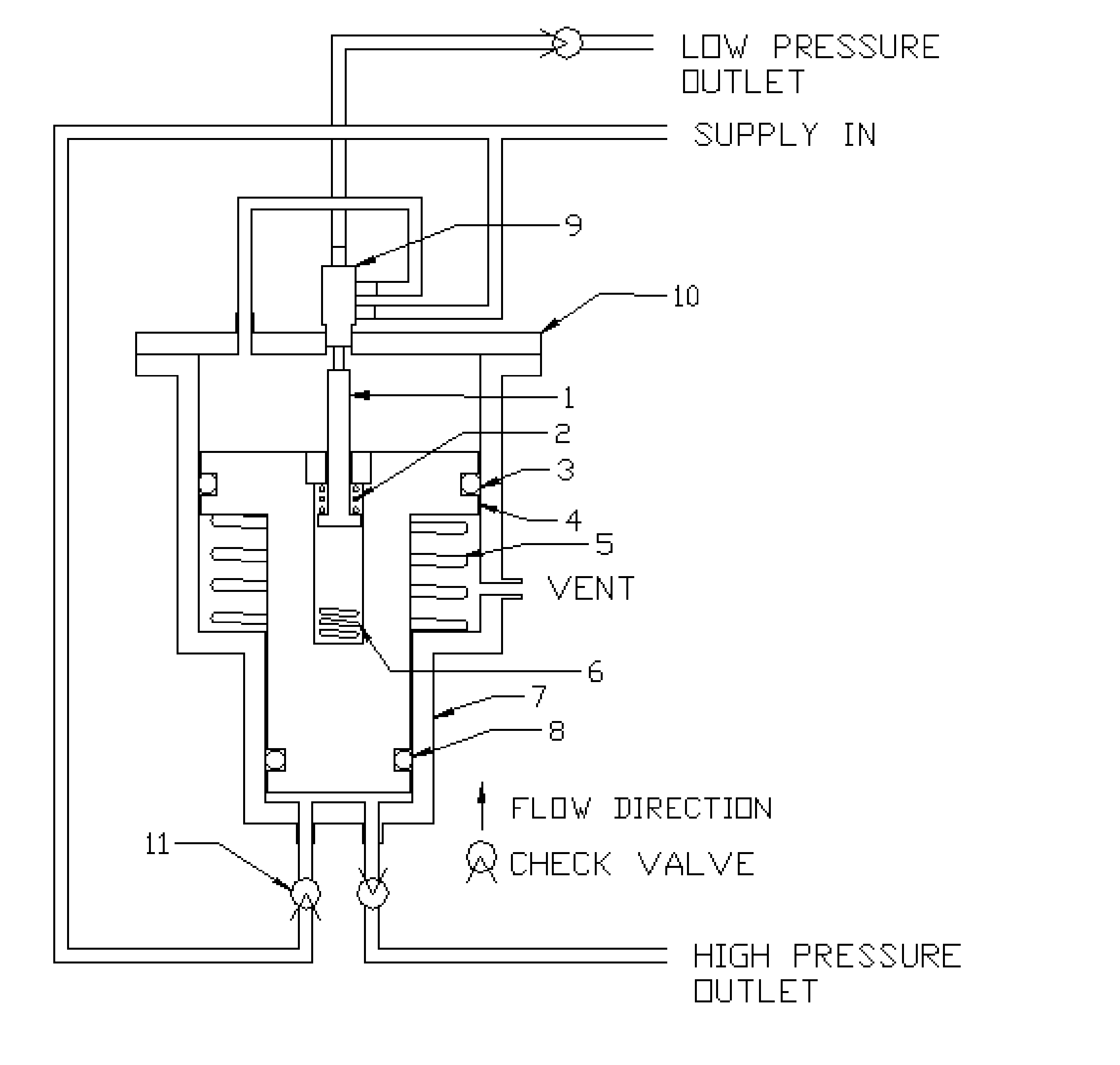
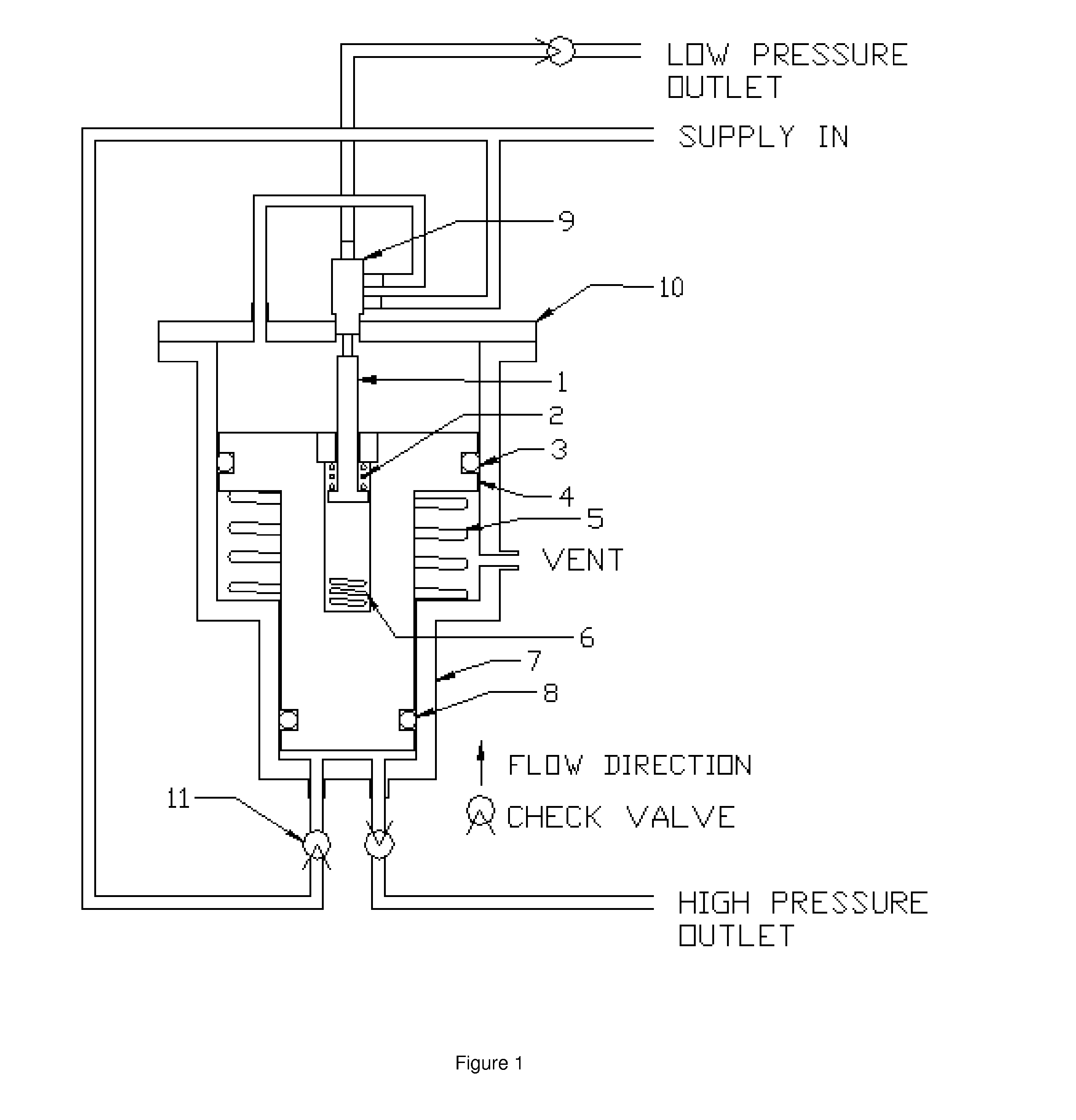
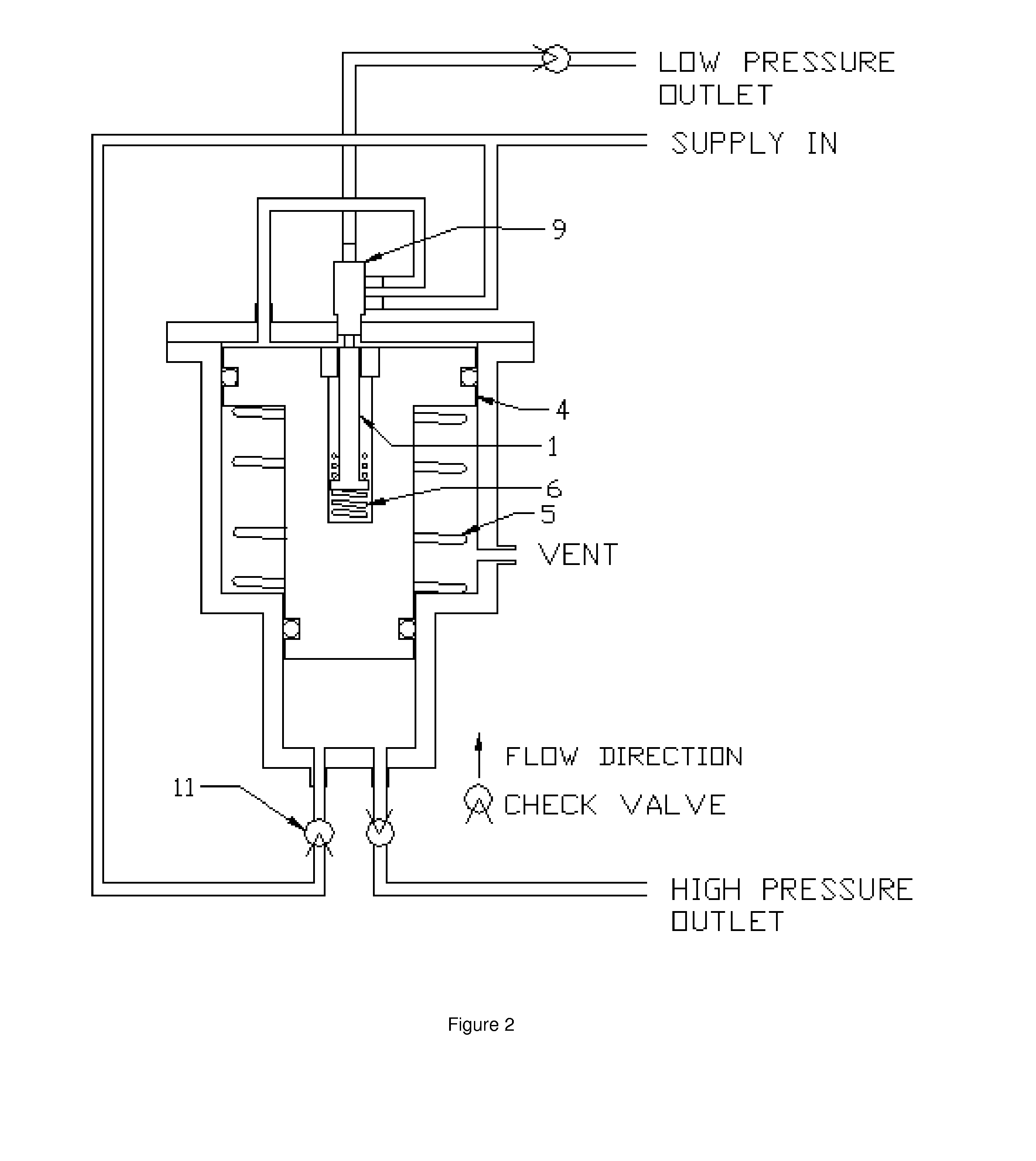
[0049]FIG. 1 shows the basic pneumatic circuit for the pressure piston type intensifier. FIG. 1 is a sectional view of the intensifier. In this particular design the intensifier uses two different piston diameters, item 3, and a cylinder, item 7, to produce a gas of higher pressure than the supply pressure. Items 3 and 8 are seals to separate gas pressures in the three chambers of the intensifier assembly. Item 1 is the flow control actuator rod; it changes the position of the 3 port valve, item 9. The control actuator rod is moved by the springs, items 2 and 6. When the piston, item 4, moves to the bottom of the cylinder the actuator rod moves pulling the 3 port valve, item 9, into a new position stopping the flow of supply gas into the large chamber and allowing the gas there to escape to the low pressure circuit. The check valves, item 11, allow the flow of gas in only one direction. Item 5 is a spring strong enough to overcome the friction of the intensifier assembly ensuring wh...


PUM


Abstract

The present invention is directed to a system for supplying gas to a pneumatic logic controlled system such as ventilator or resuscitator. The system produces a high pressure gas stream and a low pressure gas stream from an intermediate gas pressure source. The intermediate pressure source could be any oxygen supply including a chemical oxygen generator or compressor. The high pressure gas stream has the water removed from the gas stream. The high pressure gas provides an energy source to the pneumatic logic of the ventilator or a resuscitator. The output flow of the pneumatic logic is used to control the flow of the low pressure gas by means of a proportional flow control valve. The proportional flow control valve combines the signal gas flow from the pneumatic control logic and the low pressure gas.

Description

CROSS-REFERENCE TO RELATED APPLICATIONS[0001]Not ApplicableSTATEMENT REGARDING FEDERALLY SPONSORED RESEARCH OR DEVELOPMENT[0002]Not ApplicableREFERENCE TO SEQUENCE LISTING, A TABLE, OR A COMPUTER PROGRAM LISTING COMPACT DISC APPENDIX[0003]Not ApplicableBACKGROUND OF THE INVENTION[0004]Various types of pneumatically controlled ventilators or resuscitators are well-know in the art. Typical designs use a high pressure gas supply with a dew point of −85 degrees Fahrenheit at operating pressures of 30 to 80 psig. In general pneumatically controlled ventilators or resuscitators are not designed to operate with a chemical oxygen generator, which may contain small amounts of water. The Society of Automotive Engineers specification AS8010 section 3.2.2 places the limit on the amount of water in a chemical oxygen generator at 20 milligrams per liter of gas at a temperature of 70 degree Fahrenheit and 760 millimeters of mercury. This corresponds to a dew point of 77 degrees Fahrenheit. The fir...

Claims


Application Information

Patent Timeline
Patent Type & Authority Applications(United States)
IPC IPC(8): A61M16/00A61N1/00
CPCA61M16/0808A61M16/20A61M16/22A61M16/209A61M2205/8231A61M16/101A61M16/207A61M2202/0208A61M16/107A61M16/203
Inventor KLEINBECK, THOMAS R.
Owner KLEINBECK THOMAS RAYMOND
Why Eureka
Try Eureka