
Compositions For Applying To Ceramic Honeycomb Bodies

Active Publication Date: 2009-02-05
CORNING INC
View PDF53 Cites 26 Cited by
  • Summary
  • Abstract
  • Description
  • Claims
  • Application Information

AI Technical Summary

Benefits of technology

[0007]The present invention provides improved compositions for applying to honeycomb bodies. In one embodiment, the composition can be used for forming skin coatings on exterior portions of honeycomb bodies. In another embodiment, the compositions can be use as plugging mixtures for forming ceramic wall flow filters. The plugging mixtures comprise one or more rheology modifiers which, when added to the mixture formulation, provide high yield strength and low viscosity under shear. Resulting from the improved Theological properties, the plugging mixtures exhibit improved performance with respect to plugging depth, and a reduction or even elimination of the formation of dimples, pinholes or large internal voids that are significantly larger than the desired pore size in the dried or fired plugs. For example, a large internal voids has a largest length dimension of greater than or equal to 0.5 mm.

Problems solved by technology

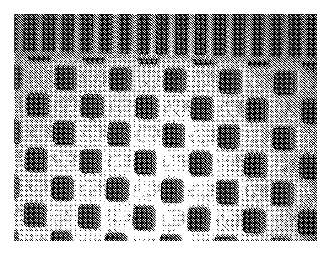
Current aluminum-titanate (AT) and cordierite plugging mixtures have resulted in the formation of large pin holes and dimples during the drying step.
On occasion, these can extended over the entire length of the plug and cause the part to be rejected by quality control procedures.
Dimpling (which can lead to leaks) has also been a known problem and is made worse with high porosity ceramics such as AT and cordierite substrates.
During the plugging process, the preformed slug of plugging mixture, which is fed into the substrate part (from the ram to the interface between the slug and the substrate) can run or slump in the reservoir of the piston / cylinder, resulting in non-uniform plugging and in some cases, unplugged areas of the substrate, as well as difficulties in manufacturing and yields.
Additionally, current plugging mixture formulations have a pot life which is short due to changes in viscosity over time.

Method used


Image

  • Compositions For Applying To Ceramic Honeycomb Bodies
  • Compositions For Applying To Ceramic Honeycomb Bodies
  • Compositions For Applying To Ceramic Honeycomb Bodies

Examples


example

[0060]To further illustrate the principles of the present invention, the following examples are put forth so as to provide those of ordinary skill in the art with a complete disclosure and description of how the plugging mixtures and methods claimed herein are made and evaluated. They are intended to be purely exemplary of the invention and are not intended to limit the scope of what the inventors regard as their invention. Unless indicated otherwise, parts are parts by weight, temperature is ° C. or is at ambient temperature, and pressure is at or near atmospheric.

[0061]In the following Examples, a number of plugging mixtures were prepared and evaluated for rheological properties including yield strength, as indicated by a resistance to slumping and deformation, and capillary viscosity. Additionally, the plugging mixtures were also evaluated for their performance properties when used to form end plugs in both cordierite and aluminum titanate honeycomb articles. In particular, the e...


PUM

PropertyMeasurementUnit
Percent by massaaaaaaaaaa
Viscosityaaaaaaaaaa

Abstract

Disclosed are compositions for applying to honeycomb bodies. The compositions can be used as plugging mixtures for forming a ceramic wall flow filter. Alternatively, the compositions can be used to form skin coatings on exterior portions of a honeycomb body. The disclosed compositions include an inorganic powder batch composition, an organic binder, a liquid vehicle, and a rheology modifier. The compositions exhibit improved rheological properties, including an increased yield strength and reduced viscosity under shear, which, among various embodiments, can enable the manufacture of sintered phase end plugs having reduced levels of dimple and pinhole formations in the final dried and fired end plugs as well as end plugs having relatively uniform and desired depths. Also disclosed are methods for forming end plugged ceramic wall flow filters from the plugging mixtures disclosed herein.

Description

RELATED APPLICATIONS [0001]This application claims the benefit of U.S. Provisional Application No. 60 / 962,715, filed Jul. 31, 2007, entitled “Compositions for Applying to Ceramic Honeycomb Bodies.”BACKGROUND [0002]The present invention relates to the manufacture of porous ceramic particulate filters, and more particularly to improved plugging mixtures and processes for sealing selected channels of porous ceramic honeycombs to form wall-flow ceramic filters.TECHNICAL BACKGROUND [0003]Ceramic wall flow filters are finding widening use for the removal of particulate pollutants from diesel or other combustion engine exhaust streams. A number of different approaches for manufacturing such filters from channeled honeycomb structures formed of porous ceramics are known. The most widespread approach is to position plugs of sealing material at the ends of alternate channels of such structures which can block direct fluid flow through the channels and force the fluid stream through the porous...

Claims


Application Information

Patent Timeline
IPC IPC(8): C04B35/64B05D7/00C09D5/34
CPCB01D2279/30C04B28/005C04B2235/3481C04B2235/3463C04B28/24C04B35/185C04B35/195C04B35/478C04B38/0006C04B38/0012C04B41/009C04B41/5024C04B41/5037C04B41/5042C04B41/85C04B41/87C04B2111/00793C04B2201/10C04B2235/3206C04B2235/3217C04B2235/3234C04B2235/3418C04B41/4539C04B41/4547C04B41/4578C04B41/5022C04B41/5089C04B41/455
Inventor BOOKBINDER, DANA CRAIGGRIFFIN, JR., JAMES ARTHURTENNENT, DAVID LAMBIEWU, LUNG-MING
Owner CORNING INC
Features
  • Generate Ideas
  • Intellectual Property
  • Life Sciences
  • Materials
  • Tech Scout
  • Unparalleled Data Quality
  • Higher Quality Content
  • 60% Fewer Hallucinations
Learn More