Through-the-wall motion detector with improved antenna

Inactive Publication Date: 2009-02-05
BAE SYST INFORMATION & ELECTRONICS SYST INTERGRATION INC
View PDF5 Cites 17 Cited by
  • Summary
  • Abstract
  • Description
  • Claims
  • Application Information

AI Technical Summary

Benefits of technology

[0032]In summary, a flat panel antenna used at a wall in a through-the-wall CW radar application is spaced from the wall by a half wavelength to eliminate the effects of the discontinuity associated with the wall to prevent receiver swamping and thus limit receiver dynamic

Problems solved by technology

In many instances, for example when detecting moving objects behind dense walls made of brick or concrete, traditional flat panel antennas may not have adequate performance because a substantial amount of energy is reflected from the first wall surface.
However, placing the antenna again

Method used


Image

  • Through-the-wall motion detector with improved antenna
  • Through-the-wall motion detector with improved antenna
  • Through-the-wall motion detector with improved antenna

Examples


Embodiment Construction

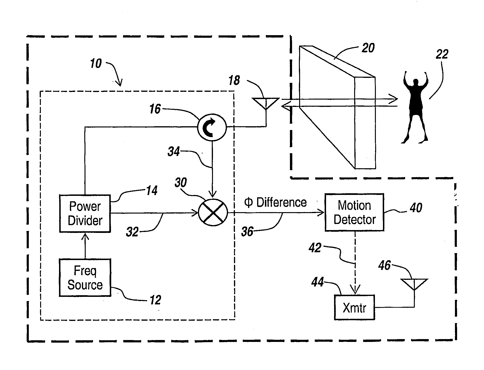
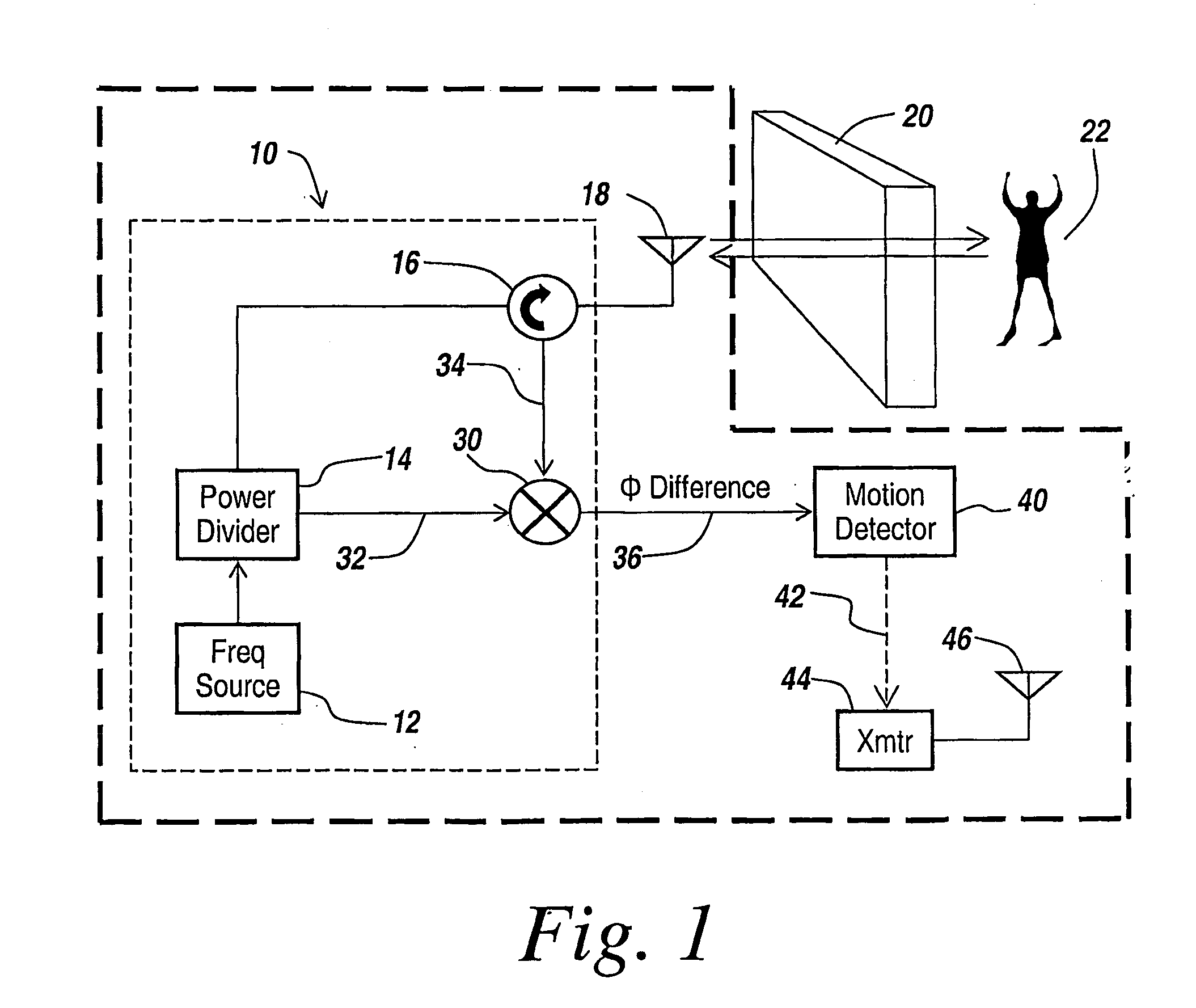
[0039]Prior to describing the subject invention and by way of background, in order to obtain a through-the-wall motion detector capable of easily detecting a person within a room, is has been found that one can detect these individuals because they are typically in motion. To detect individuals behind a wall, the through-the-wall system employs a simple CW radar with a directional antenna. In one embodiment, the transmitter for this CW radar employs a circulator that is coupled to a directional antenna so that a CW beam is projected through the wall and into the room. Returns from the CW beam arrive at the same antenna and are split off by the circulator. A reduced power replica from the transmitted signal is mixed with the returns from the antenna. Changes in the phase difference between the two signals indicate motion, and thus the presence of an individual behind the wall. In one embodiment, the summing is performed at a mixer, with slight phase differences indicating motion of a...


PUM


Abstract

A flat panel antenna used at a wall in a through-the-wall CW radar application is spaced from the wall by a half wavelength to eliminate the effects of energy reflected by the wall back to the antenna. In one embodiment, a ½-wavelength dielectric absorbing material insert is placed adjacent the flat panel antenna, which allows the flat panel antenna to be pressed against the wall for antenna stabilization, with the index of refraction of the material desirably being 3.

Description

RELATED APPLICATIONS[0001]This Application claims rights under 35 USC § 119(e) from U.S. Provisional Application Ser. No. 60 / 726,959 filed Oct. 14, 2005, the contents of which are incorporated herein by reference.[0002]This application is related to PCT Patent Application: US2004 / 30116 filed Sep. 14, 2004 by Paul D. Zemany, Jr. of Amherst, N. H. and Eldon Sutphin of Merrimack, N. H., entitled “Method and Apparatus for Through-the-Wall Motion Detection Utilizing CW Radar,” the contents of which is incorporated herein by reference.FIELD OF THE INVENTION[0003]This invention relates to using CW radar to detect motion of objects behind a wall and more particularly to a system with an improved antenna for such use.BACKGROUND OF THE INVENTION[0004]Oftentimes it is desirable to be able to detect individuals within, for instance, a burning building or enemy combatants or troops behind a wall. Moreover, in some instances police can utilize through-wall sensing systems to be able to detect the...

Claims


Application Information

Patent Timeline
IPC IPC(8): G01S13/00
CPCG01S13/56G01S13/888H01Q21/065H01Q1/22H01Q1/40H01Q1/1221
Inventor ZEMANY, PAUL D.
Owner BAE SYST INFORMATION & ELECTRONICS SYST INTERGRATION INC
Why Eureka
Try Eureka