Antistatic Coating For Surfaces Made Of Metal Materials And Dielectric Materials Or Of Dielectric Materials Only In Particular Antenna Surfaces And Method Of Application Thereof

a technology of dielectric materials and metal materials, applied in the direction of ion implantation coating, antennas, disturbance protection, etc., can solve the problems of affecting the operation of the antenna, affecting the natural behaviour of the material, and affecting the effect of the antenna

Inactive Publication Date: 2009-02-05
LEONARDO
View PDF1 Cites 3 Cited by
  • Summary
  • Abstract
  • Description
  • Claims
  • Application Information

AI Technical Summary

Benefits of technology

[0007]The proposal described in synthesis relates to the application of a thin film coating adapted for transferring antistatic characteristics to the surface on which it is placed. Such properties allows preventing electrical charge accumulations on an insulating surface from reaching such a level as to exceed a threshold level (called dielectric rigidity, typical of every insulating material) wherein a sudden and sometimes destructive discharge phenomenon in the material body itself triggers, which is crossed by an electrical current with negative results. The coating proposed, mostly consisting of a thin film of pure germanium and partly or totally stoichiometric oxides thereof, reduces this phenomenon up to annul it, imparting a light electrical conductivity to the surface it is deposited on, without altering or interfering with the operation of the antenna on which it is deposited. This property is especially important since between the surfaces of any satellite into orbit, subject to the charge accumulation problem, those of an active antenna are especially concerned by this phenomenon, which mainly concerns the outer rather than the inner surfaces, and they are also the most damaged by the same, since: 1) if the conditions are such as to cause an arc discharge with a high potential between outer surface of the antenna and surrounding spatial plasma, this can bring to a progressive erosion of the material forming the outer layer of the antenna itself during its operating life. This erosion could impair the structural integrity of the antenna or that of any metal elements arranged along the outer surface thereof, which considerably affect the performance thereof. 2) As an alternative, the uninterrupted presence of the micro-discharge phenomenon and of the electromagnetic waves that this phenomenon can generate, located in the emission surface of a radio signal with known frequency, width and gain, and intended for performing the primary satellite mission, could cause a degradation of the emitted signal and thus of the overall electrical performance of the antenna.

Problems solved by technology

When this value exceeds that of threshold, called dielectric rigidity, typical of every insulating material, a discharge phenomenon triggers, which could have destructive effects and interfere with the antenna in the operation thereof.
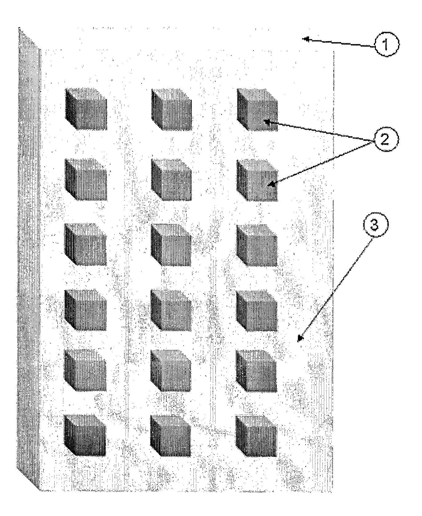
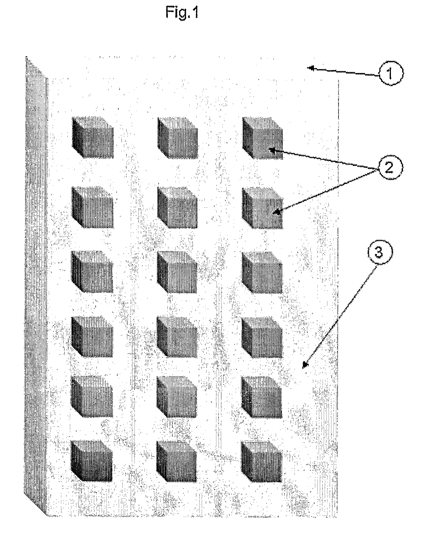
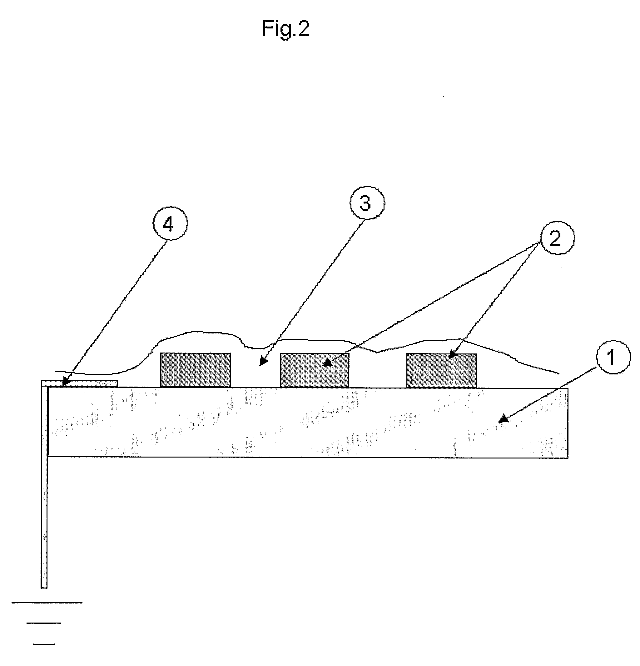
The application of the thin germanium film on all the antenna surface, both on a metal material and optionally on the dielectric material present on the exposed surface, makes such surface unipotential and prevents local accumulation of charges, as this film is partly conductive.
The germanium coating application on the surfaces of an antenna fully falls within the construction process of the antenna itself and can be regarded to all effects as a functional coating, meaning that its presence alters the natural behaviour of the material, which would otherwise be that of charging and discharging in repeated cycles with destructive end results.
Even though the application is also allowed with evaporation systems, the coatings that can be obtained with this deposition system are not very adhering and coherent, and therefore they ensure coating durability not in line with the intended uses, which also envisage certain manual handling.

Method used


Image

  • Antistatic Coating For Surfaces Made Of Metal Materials And Dielectric Materials Or Of Dielectric Materials Only In Particular Antenna Surfaces And Method Of Application Thereof
  • Antistatic Coating For Surfaces Made Of Metal Materials And Dielectric Materials Or Of Dielectric Materials Only In Particular Antenna Surfaces And Method Of Application Thereof
  • Antistatic Coating For Surfaces Made Of Metal Materials And Dielectric Materials Or Of Dielectric Materials Only In Particular Antenna Surfaces And Method Of Application Thereof

Examples


Embodiment Construction

[0007]The proposal described in synthesis relates to the application of a thin film coating adapted for transferring antistatic characteristics to the surface on which it is placed. Such properties allows preventing electrical charge accumulations on an insulating surface from reaching such a level as to exceed a threshold level (called dielectric rigidity, typical of every insulating material) wherein a sudden and sometimes destructive discharge phenomenon in the material body itself triggers, which is crossed by an electrical current with negative results. The coating proposed, mostly consisting of a thin film of pure germanium and partly or totally stoichiometric oxides thereof, reduces this phenomenon up to annul it, imparting a light electrical conductivity to the surface it is deposited on, without altering or interfering with the operation of the antenna on which it is deposited. This property is especially important since between the surfaces of any satellite into orbit, sub...


PUM

PropertyMeasurementUnit
pressureaaaaaaaaaa
frequencyaaaaaaaaaa
dielectricaaaaaaaaaa

Abstract

Thin film coating for transferring antistatic characteristics to the surface on which it is placed, in particular antenna surfaces, in order to prevent electrical charge accumulations on it and discharge phenomenon.

Description

[0001]Artificial satellites operate in an environment that can be described by the definition of four environmental features: neutral atmosphere (that typical of the Earth, optionally residual at the heights the satellite moves), plasma (made of multiple components typical of the satellite, such as nozzles and motors, or coming from the motion thereof, such as discharges and ionisation), corpuscular environment (consisting of micro meteorites, orbital debris and all the particles detached from the satellite itself) and finally, radiative environment (resulting both from electromagnetic waves and from flows of charged particles, mainly originated by the sun activity).[0002]As regards plasmas, these represent a current flow towards the satellite surfaces, and towards the exposed parts of the power subsystems onboard thereof. Intrinsic unbalances in this current flow arise from the accumulation of charges on the surfaces exposed to the plasma. The charge may also be caused by photoelec...

Claims


Application Information

Patent Timeline
Patent Type & Authority Applications(United States)
IPC IPC(8): H01Q1/32C22C28/00C09K3/16H01Q13/00
CPCB64G1/226B64G1/52C09K3/16C23C14/021C23C14/022Y10T29/49016C23C14/205C23C30/00H01Q1/002H01Q1/288C23C14/165
Inventor CAPECE, PASQUALEIVAGNES, MARCO MANUEL
Owner LEONARDO
Why Eureka
Try Eureka