[0013] In accordance with one embodiment of the present invention, an
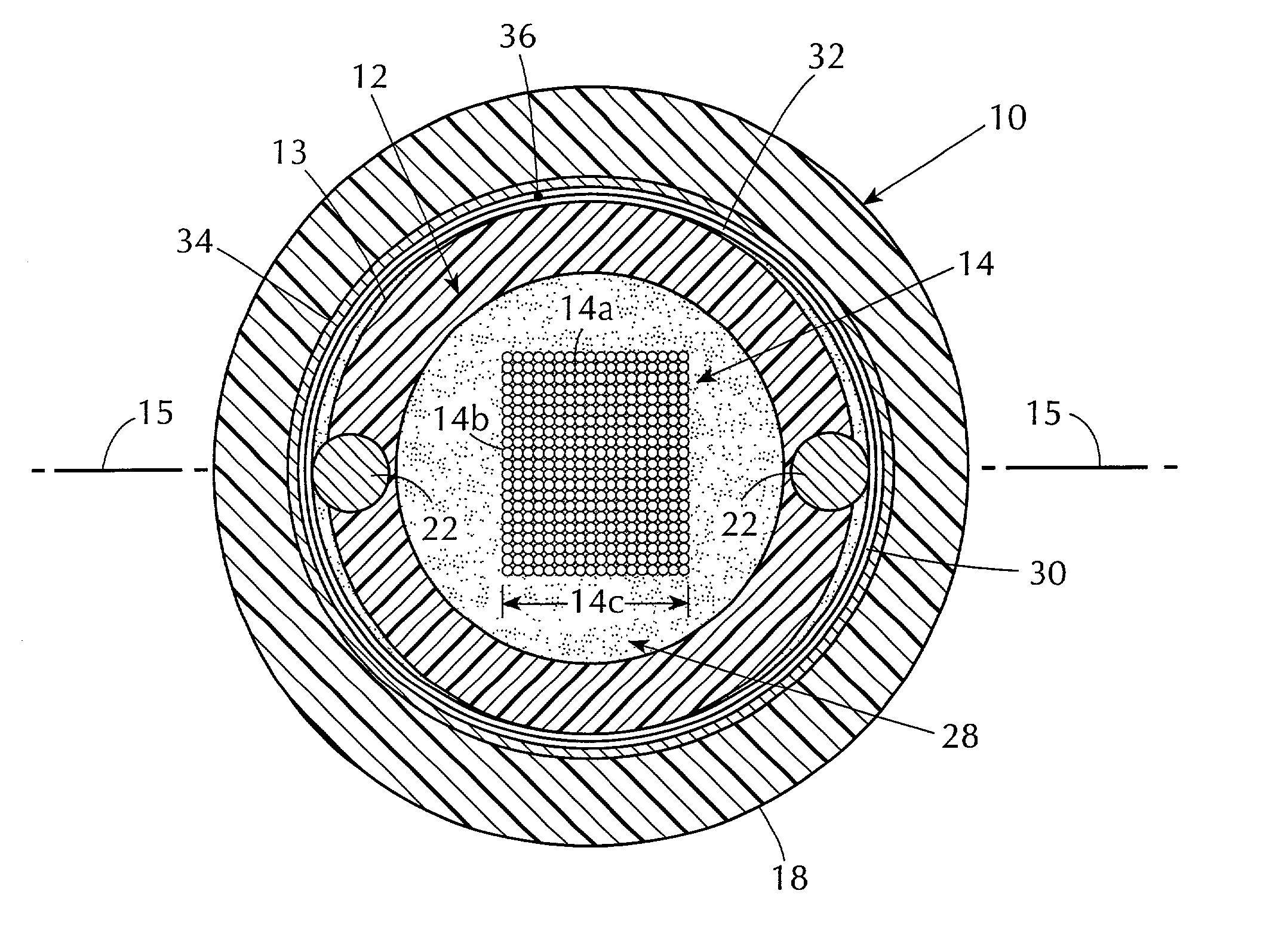
optical fiber cable core comprises a buffer tube of a plastic material loosely containing and completely encircling at least one optical fiber. The buffer tube has a longitudinal axis, a nominal outer periphery, and has at least two strength members tightly coupled to the buffer tube and with surface portions thereof
proximate the nominal outer periphery of the buffer tube. If the strength members have surface portions outwardly of the nominal periphery of the buffer tube, lip portions of buffer tube material extend towards each other and engage the strength members. The strength members extend longitudinally of the core and substantially parallel to the longitudinal axis of the buffer tube. Thus, each strength member is partially embedded in the buffer tube such that the lip portions extend over and engage a portion of the outer surface of the strength members. Buffer tube material partially surrounding and engaging the strength members, including the lip portions, applies radially inward forces to the strength members, thereby tightly
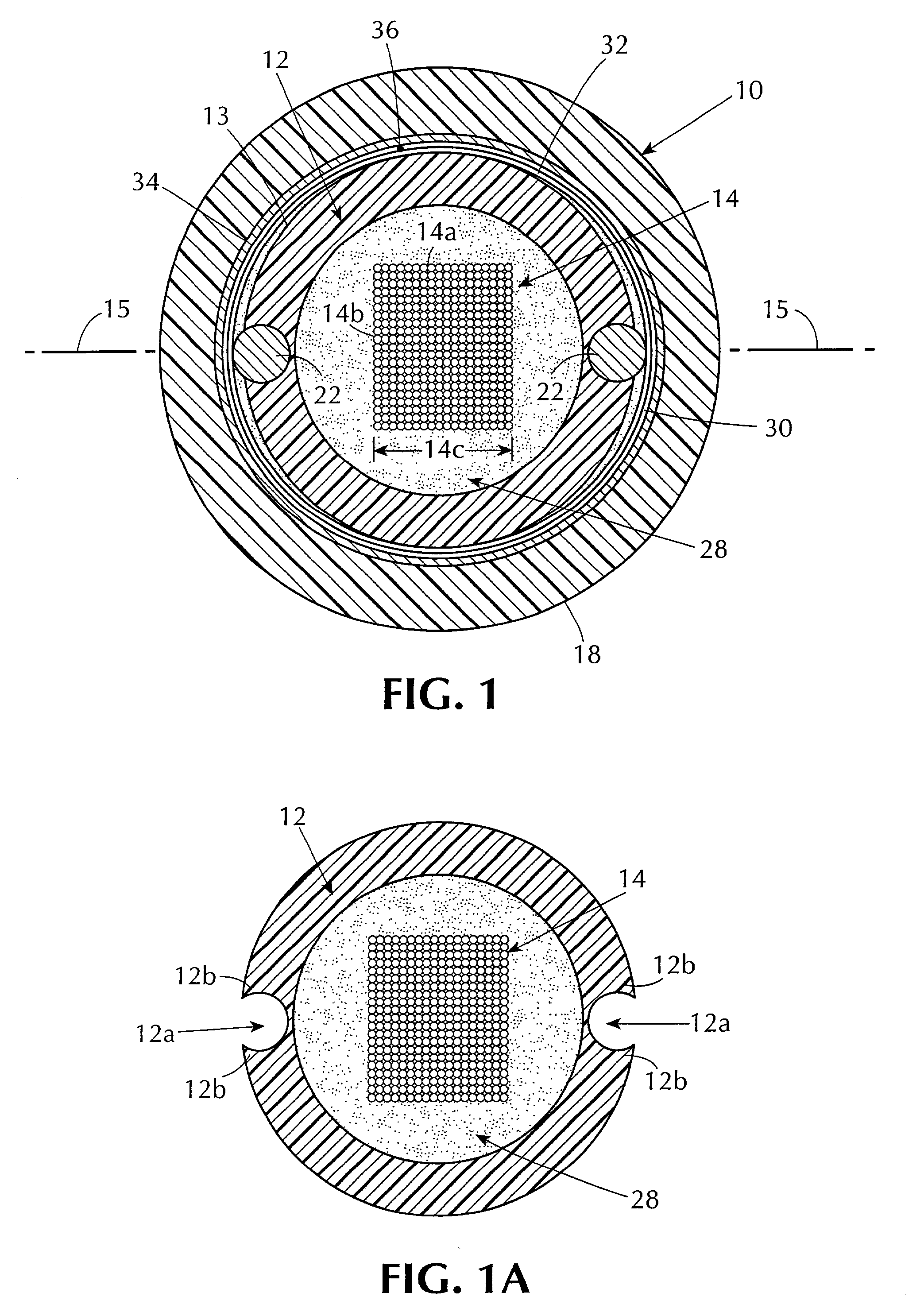
coupling the strength members to the buffer tube material, to provide resistance to contraction and expansion forces, as described in the '097 patent. The radially outermost surface portion of each strength member, i.e. in the radial direction with respect to the longitudinal axis of the buffer tube, may be substantially tangent to or protrude beyond the outer surface of the buffer tube such that less than half of the outer surface of each of the strength members protrudes beyond the nominal outer periphery of the buffer tube. If portions of the outer surface of the strength members protrude outwardly of the nominal periphery of the buffer tube, longitudinal portions of one or both of the strength members can be easily pulled away from the buffer tube by pushing the buffer tube material adjacent to the strength members, e.g. the lips, away from the strength members by one's fingers without the use of tools. Removal of one or both of the strength members enables midspan access to the optical fiber or fibers within the buffer tube without
cutting the strength members or damaging the
structural integrity of the tube. Also, since the strength members are visible, they can be avoided during slitting of the buffer tube by positioning the blade of the slitting tool between the strength members. Therefore, removal of the strength members may not be required. Of course, if it is desired to
cut the strength members during splicing of the optical fibers, that can be easily done, as well.
[0016] Preferably, less than about 20% and more preferably, less than about 10%, of the outer surface of each of the strength members protrudes beyond the nominal outer periphery of the buffer tube. However, due to manufacturing tolerances, a thin film of buffer tube material, which can easily be removed and which does not obscure the strength members, may cover the outermost surface portions of the strength members. The film has a thickness which is small compared to the wall thickness of the buffer tube wall. With or without the film, the strength members can be readily located and the desired
coupling between the strength members and the buffer tube is obtained.
[0017] By so
coupling the strength members to the buffer tube, the resistance of the strength members to compression forces is improved because the buffer tube resists bending and kinking of the strength members described in the '097 patent. Thus, although the methods described in the '097 patent, e.g.
adhesive or a cord, can also be used with the embodiments of the invention to
resist bending and kinking and thereby increase the compression resistance of strength members of a small diameter, the coupling of the strength members to the buffer tube provided by the invention can be sufficient, by itself, to provide the desired resistance to bending and kinking especially if the strength-member-buffer
tube structure is encircled by an extruded layer of plastic material contacting the buffer tube and the strength members.
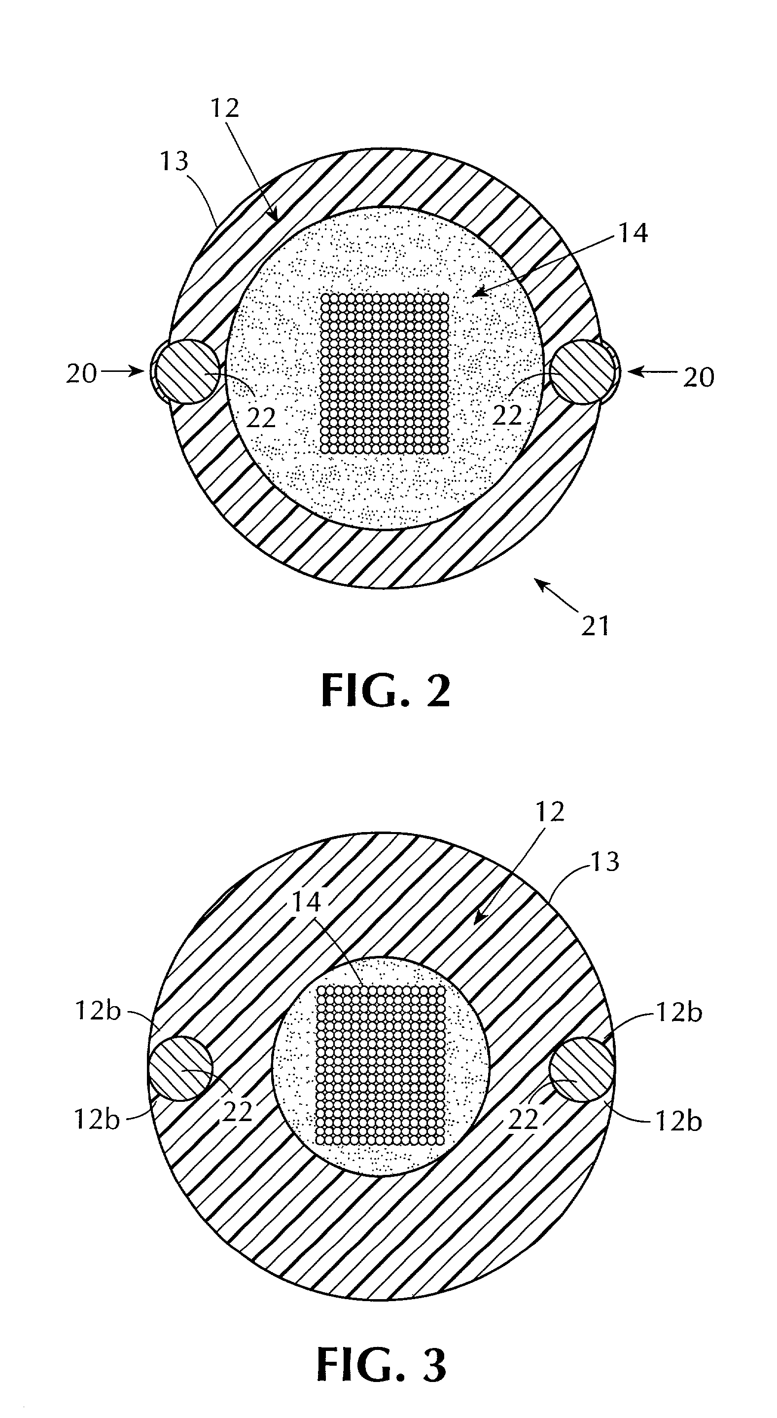
[0020] If it is necessary to accommodate the strength members, e.g. if the diameter of the strength members is such that the buffer tube wall is weakened, the buffer tube of the present invention may have thicker walls and have a larger diameter than conventional buffer tubes. This could prevent the use of conventional slitting tools to
gain midspan access, such conventional tools being designed to slit buffer tubes having a relatively small wall thickness. In such case, the buffer tube can be made with two
layers, an inner tubular portion and an outer tubular portion, each with a radial dimension which can be slit by a conventional tool. With two such
layers, preferably, the inner tubular portion is coated, prior to
extrusion of the outer tubular portion over the coated inner portion, with a material which permits the inner and outer portions to be pulled apart easily in a direction perpendicular to their adjacent surfaces, but which does not significantly reduce the resistance of the two portions to slippage relative to each other in the direction longitudinally of the tubes. Portions of the outer tubular portion can then be easily removed from the inner tubular portion, which may be of a conventional thickness and diameter, enabling the use of conventional slitting tools to
gain access to the optical fibers through the inner tubular portion.
[0022] Preferably, the space within the buffer tube not occupied by the optical fibers or optical ribbon, are filled with a water blocking material, such as a gel, which is substantially incompressible and which resists radially inward forces applied to the buffer tube and hence, the strength members. In this embodiment, radially inward forces applied by the jacket, or by a cord as described in the '097 patent, increases the coupling between the strength members and the buffer tube.
[0024] The manufacture of the reinforced buffer tube can include first extruding an inner tubular portion and then applying the strength members while extruding, with heating, an outer tubular portion over the inner tubular portion. The thickness of the outer tubular portion is selected so that the strength members are positioned within the outer tubular portion with portions of the outer surface of the strength members closely adjacent to an other surface of the outer tubular portion. As the outer tubular portion cools it contracts, thereby positioning the strength members substantially tangent to or protruding beyond the nominal outer periphery of the buffer tube, as described above, and becoming tightly coupled to the outer and inner tubular portions. As described hereinbefore, prior to
extrusion of the outer tubular portion, the inner tubular portion may be coated with a material which enables easy removal of the outer tubular portion from the inner tubular portion and yet resists longitudinal slipping between the inner and outer tubes so that conventional slitting tools can be used to gain midspan access to the optical fibers through the inner tubular portion.

