

Retardation film, polarizing plate, and liquid crystal display device comprising it
a technology of retardation film and polarizing plate, which is applied in the direction of polarising elements, thin material processing, instruments, etc., can solve the problems of color shift in oblique directions that cannot be solved in sufficient time, viewing angle-dependent light leakage, and color shift in oblique directions in the black state. achieve the effect of reducing the color shi
- Summary
- Abstract
- Description
- Claims
- Application Information
AI Technical Summary
Benefits of technology
Problems solved by technology
Method used
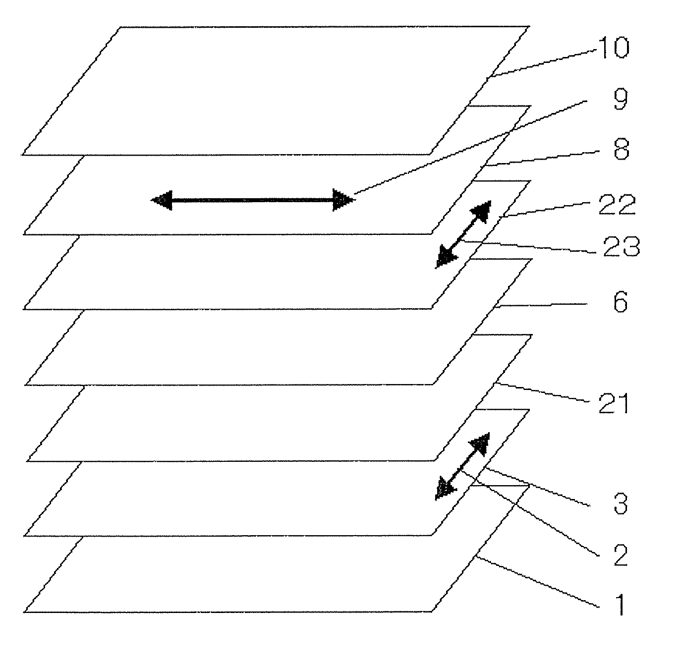
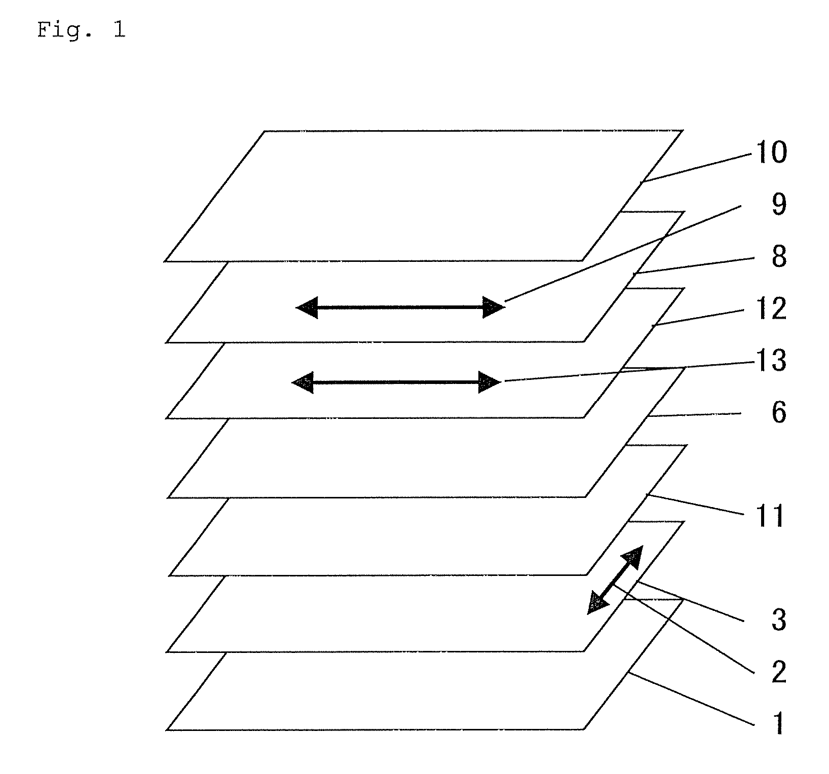
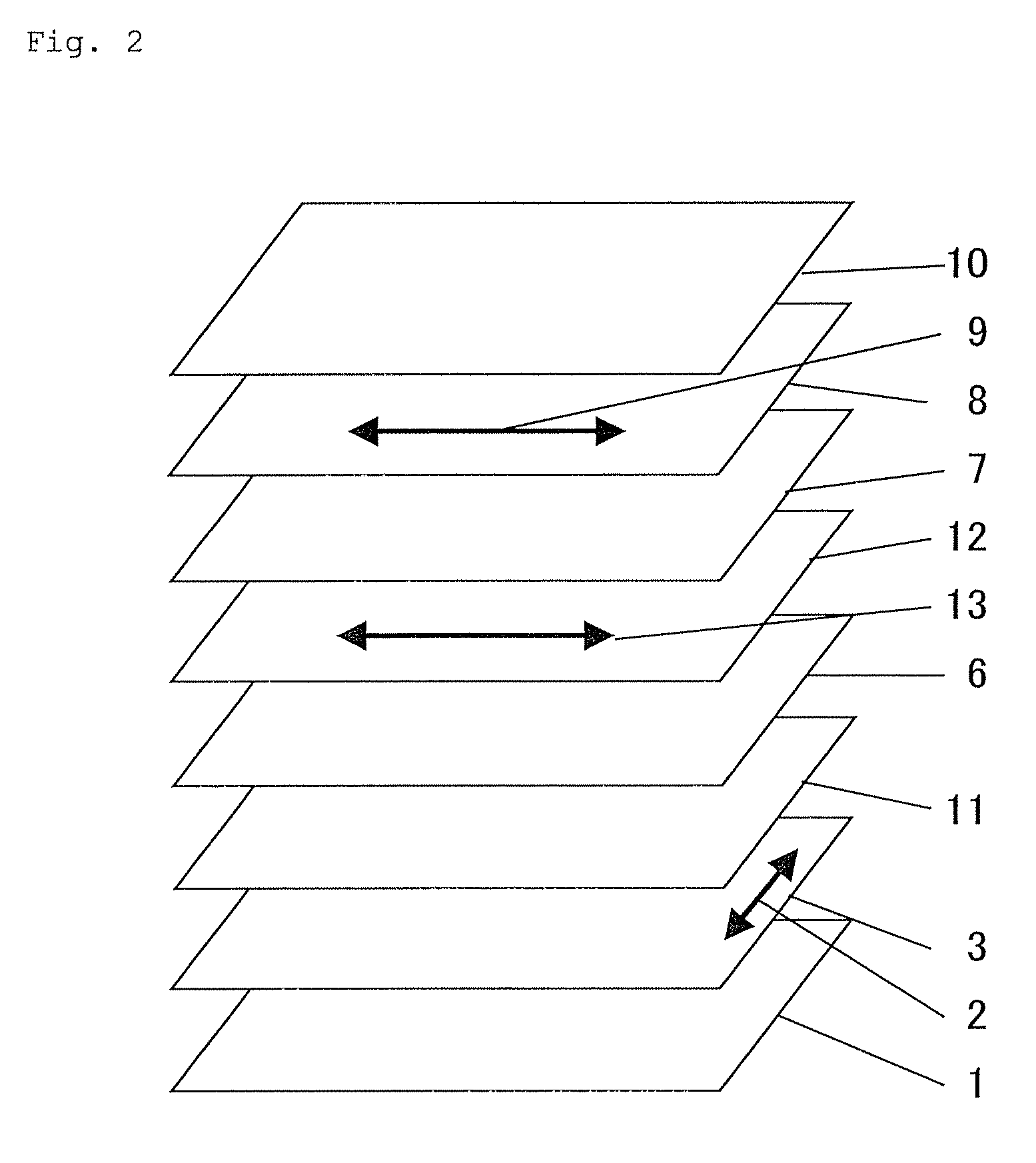
Image

Examples
example 1-2
[0401]A commercial cellulose acetate film (thickness: 80 μm; FUJITAC TD80UF produced by FUJIFILM) was led to pass through a dielectric heating roll at 60° C. whereby the film surface temperature was elevated up to 40° C.; and then an alkali solution A having the formulation mentioned below was applied onto it in an amount of 14 ml / m2, using a bar coater. Then, this was kept staying under a steam far-IR heater (by Noritake Company) heated at 110° C. for 10 seconds, and thereafter pure water was applied to it in an amount of 3 ml / m2, also using a bar coater. In this stage, the film temperature was 40° C. Next, this was rinsed with water with a fountain coater and dewatered with an air knife, and this operation was repeated three times; and then this was kept staying in a drying zone at 70° C. for 2 seconds, and thus dried.
Potassium hydroxide 4.7 mas. pts.Water15.7 mas. pts.Isopropanol64.8 mas. pts.Propylene glycol14.9 mas. pts.C16H33O(CH2CH2O)10H (surfactant) 1.0 mas. pt.
[0402]An alig...
PUM
 Abstract
Description
Claims
Application Information